NISSAN PICK-UP 1998 Repair Manual
Manufacturer: NISSAN, Model Year: 1998, Model line: PICK-UP, Model: NISSAN PICK-UP 1998Pages: 1659, PDF Size: 53.39 MB
Page 661 of 1659
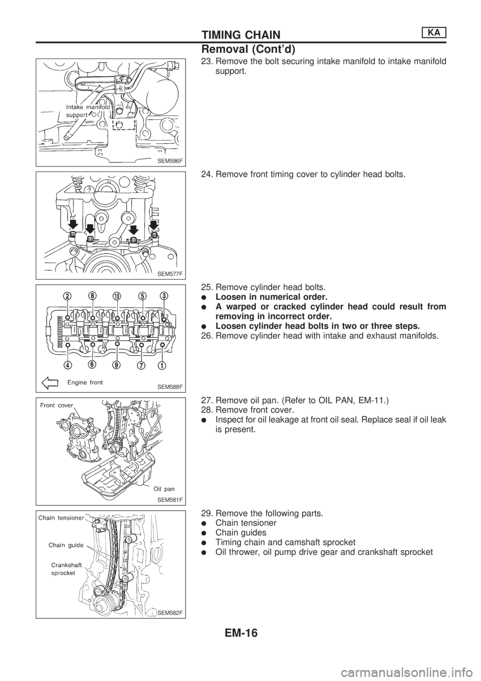
23. Remove the bolt securing intake manifold to intake manifold
support.
24. Remove front timing cover to cylinder head bolts.
25. Remove cylinder head bolts.
lLoosen in numerical order.
lA warped or cracked cylinder head could result from
removing in incorrect order.
lLoosen cylinder head bolts in two or three steps.
26. Remove cylinder head with intake and exhaust manifolds.
27. Remove oil pan. (Refer to OIL PAN, EM-11.)
28. Remove front cover.
lInspect for oil leakage at front oil seal. Replace seal if oil leak
is present.
29. Remove the following parts.
lChain tensioner
lChain guides
lTiming chain and camshaft sprocket
lOil thrower, oil pump drive gear and crankshaft sprocket
SEM596F
SEM577F
SEM588F
SEM581F
SEM582F
TIMING CHAINKA
Removal (Cont'd)
EM-16
Page 662 of 1659
Inspection
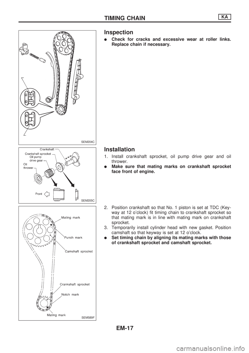
lCheck for cracks and excessive wear at roller links.
Replace chain if necessary.
Installation
1. Install crankshaft sprocket, oil pump drive gear and oil
thrower.
lMake sure that mating marks on crankshaft sprocket
face front of engine.
2. Position crankshaft so that No. 1 piston is set at TDC (Key-
way at 12 o'clock) fit timing chain to crankshaft sprocket so
that mating mark is in line with mating mark on crankshaft
sprocket.
3. Temporarily install cylinder head with new gasket. Position
camshaft so that keyway is set at 12 o'clock.
lSet timing chain by aligning its mating marks with those
of crankshaft sprocket and camshaft sprocket.
SEM204C
SEM205C
SEM589F
TIMING CHAINKA
EM-17
Page 663 of 1659
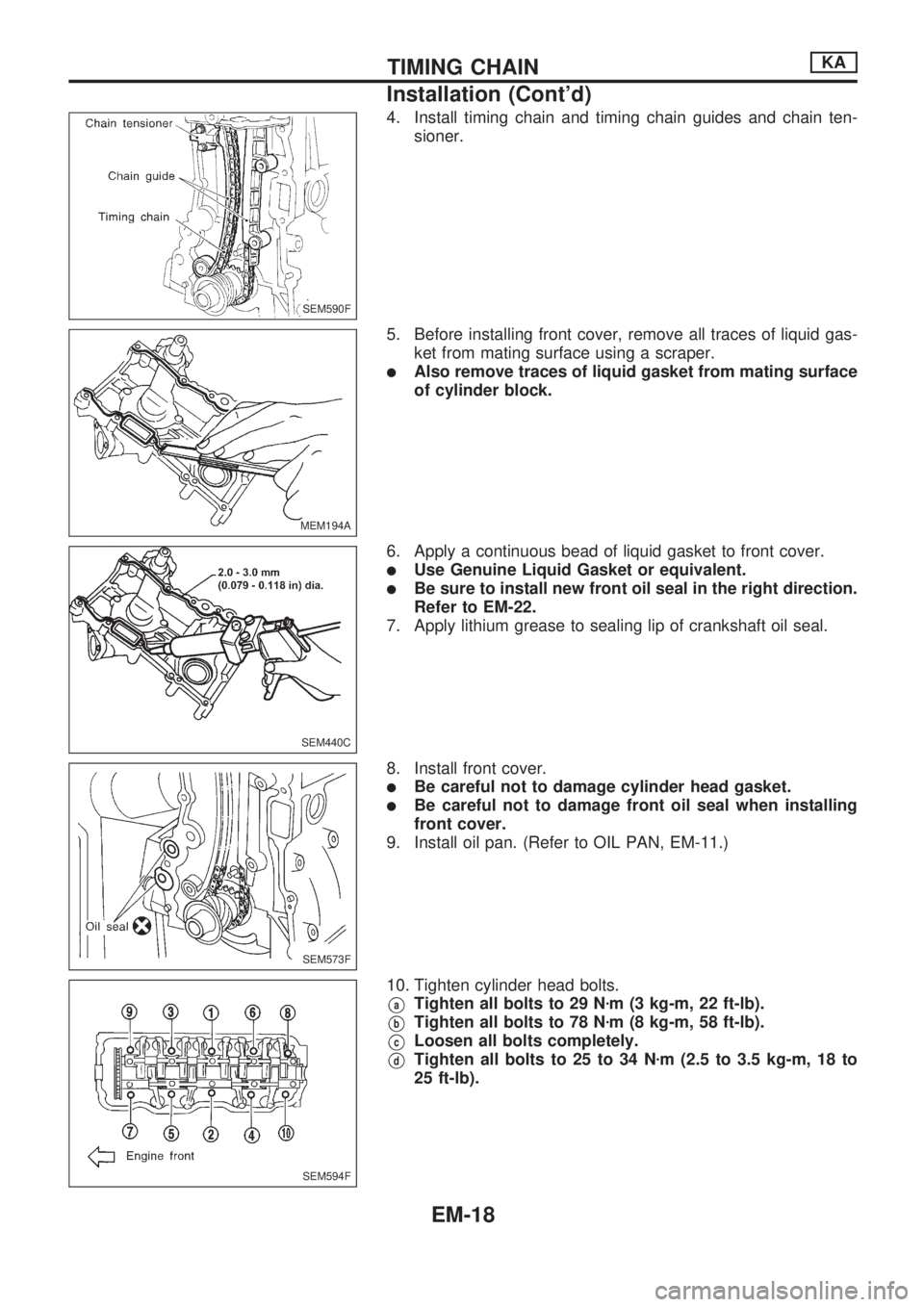
4. Install timing chain and timing chain guides and chain ten-
sioner.
5. Before installing front cover, remove all traces of liquid gas-
ket from mating surface using a scraper.
lAlso remove traces of liquid gasket from mating surface
of cylinder block.
6. Apply a continuous bead of liquid gasket to front cover.
lUse Genuine Liquid Gasket or equivalent.
lBe sure to install new front oil seal in the right direction.
Refer to EM-22.
7. Apply lithium grease to sealing lip of crankshaft oil seal.
8. Install front cover.
lBe careful not to damage cylinder head gasket.
lBe careful not to damage front oil seal when installing
front cover.
9. Install oil pan. (Refer to OIL PAN, EM-11.)
10. Tighten cylinder head bolts.
VaTighten all bolts to 29 Nzm (3 kg-m, 22 ft-lb).
VbTighten all bolts to 78 Nzm (8 kg-m, 58 ft-lb).
VcLoosen all bolts completely.
VdTighten all bolts to 25 to 34 Nzm (2.5 to 3.5 kg-m, 18 to
25 ft-lb).
SEM590F
MEM194A
SEM440C
SEM573F
SEM594F
TIMING CHAINKA
Installation (Cont'd)
EM-18
Page 664 of 1659
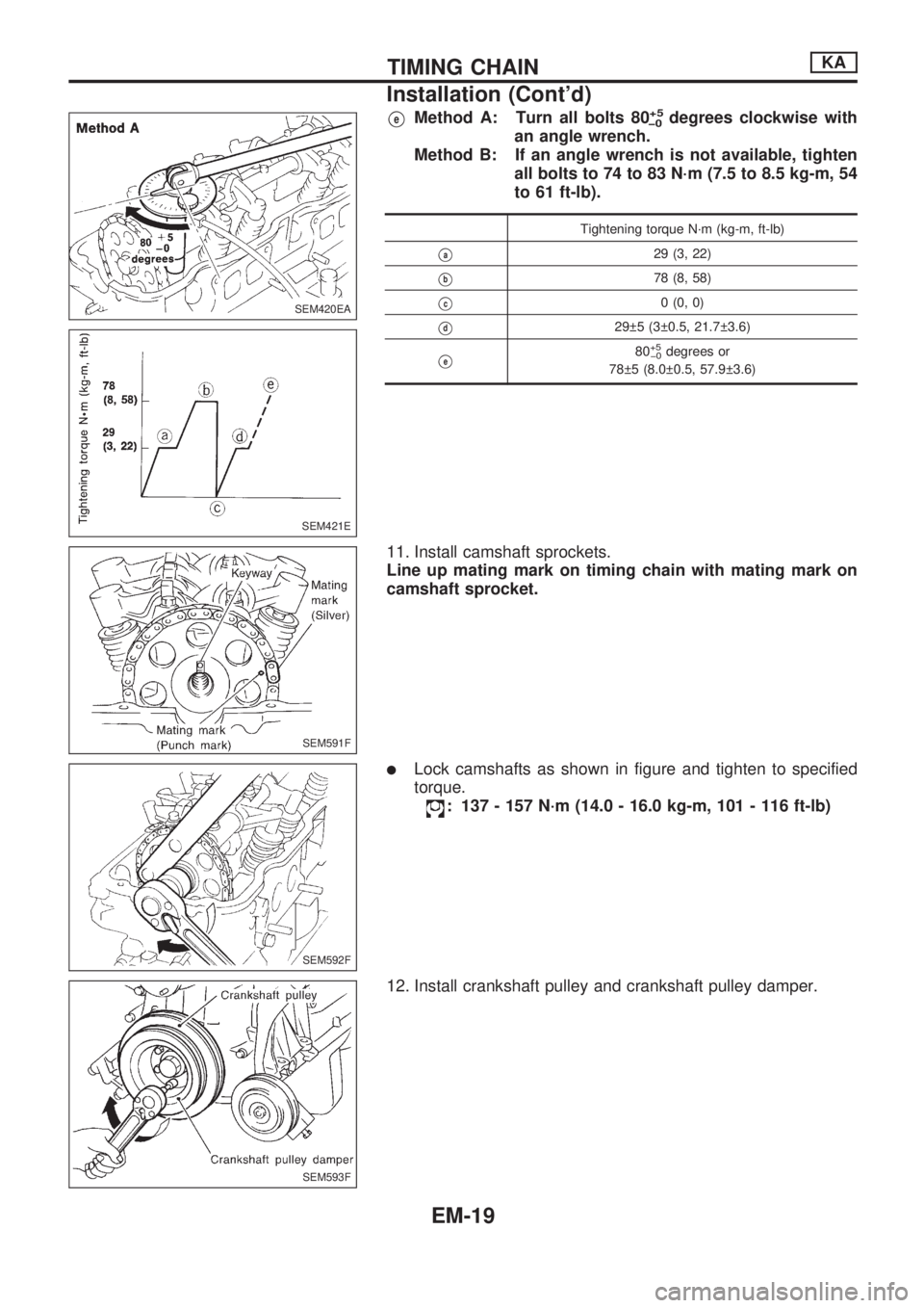
VeMethod A: Turn all bolts 80+5
þ0degrees clockwise with
an angle wrench.
Method B: If an angle wrench is not available, tighten
all bolts to 74 to 83 N´m (7.5 to 8.5 kg-m, 54
to 61 ft-lb).
Tightening torque N´m (kg-m, ft-lb)
Va29 (3, 22)
Vb78 (8, 58)
Vc0 (0, 0)
Vd29 5 (3 0.5, 21.7 3.6)
Ve80+5
þ0degrees or
78 5 (8.0 0.5, 57.9 3.6)
11. Install camshaft sprockets.
Line up mating mark on timing chain with mating mark on
camshaft sprocket.
lLock camshafts as shown in figure and tighten to specified
torque.
: 137 - 157 N´m (14.0 - 16.0 kg-m, 101 - 116 ft-lb)
12. Install crankshaft pulley and crankshaft pulley damper.
SEM420EA
SEM421E
SEM591F
SEM592F
SEM593F
TIMING CHAINKA
Installation (Cont'd)
EM-19
Page 665 of 1659
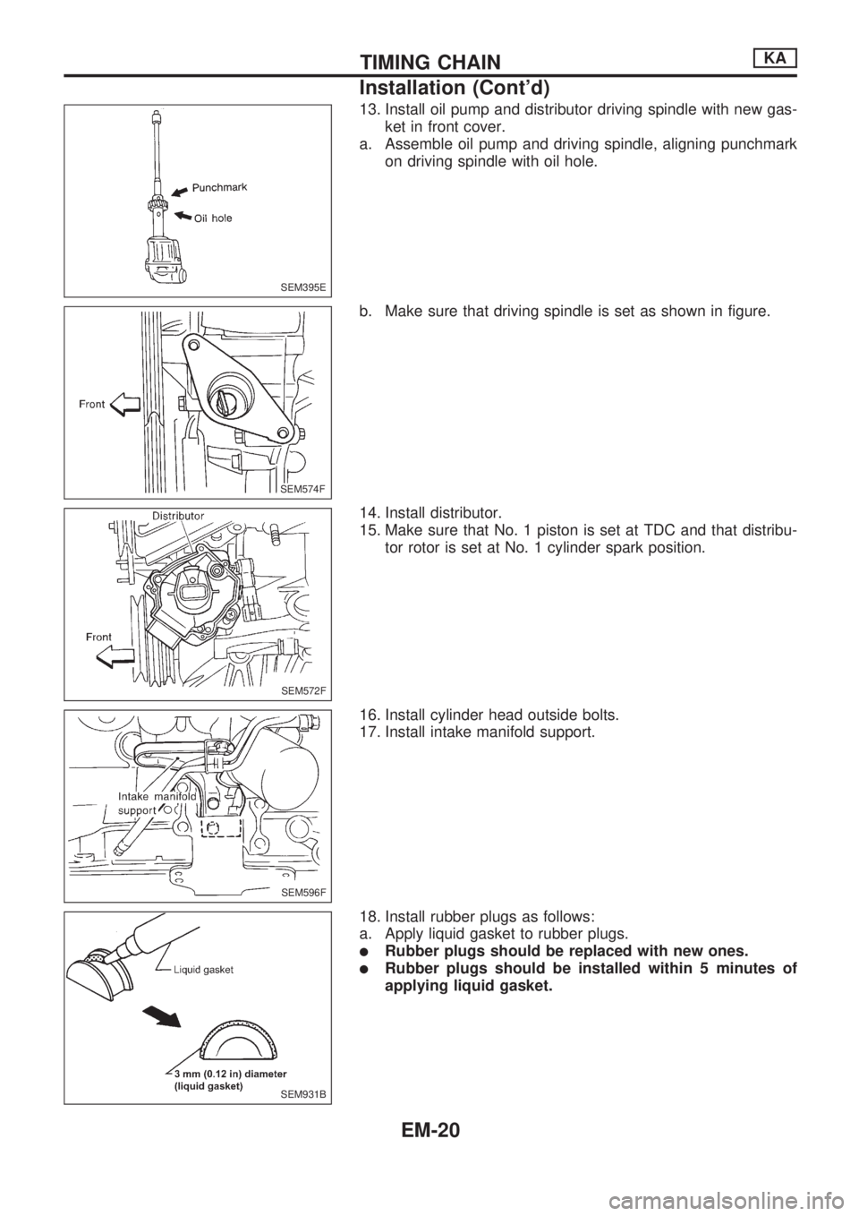
13. Install oil pump and distributor driving spindle with new gas-
ket in front cover.
a. Assemble oil pump and driving spindle, aligning punchmark
on driving spindle with oil hole.
b. Make sure that driving spindle is set as shown in figure.
14. Install distributor.
15. Make sure that No. 1 piston is set at TDC and that distribu-
tor rotor is set at No. 1 cylinder spark position.
16. Install cylinder head outside bolts.
17. Install intake manifold support.
18. Install rubber plugs as follows:
a. Apply liquid gasket to rubber plugs.
lRubber plugs should be replaced with new ones.
lRubber plugs should be installed within 5 minutes of
applying liquid gasket.
SEM395E
SEM574F.SEM574F
SEM572F
SEM596F
SEM931B
TIMING CHAINKA
Installation (Cont'd)
EM-20
Page 666 of 1659
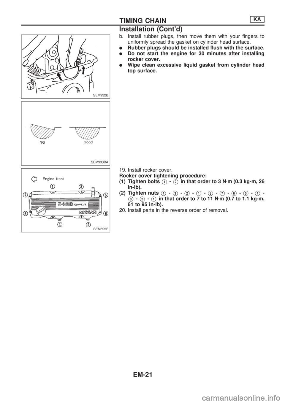
b. Install rubber plugs, then move them with your fingers to
uniformly spread the gasket on cylinder head surface.
lRubber plugs should be installed flush with the surface.
lDo not start the engine for 30 minutes after installing
rocker cover.
lWipe clean excessive liquid gasket from cylinder head
top surface.
19. Install rocker cover.
Rocker cover tightening procedure:
(1) Tighten bolts
V1-V2in that order to 3 N´m (0.3 kg-m, 26
in-lb).
(2) Tighten nuts
V4-V3-V2-V1-V8-V7-V6-V5-V4-
V3-V2-V1in that order to 7 to 11 Nzm (0.7 to 1.1 kg-m,
61 to 95 in-lb).
20. Install parts in the reverse order of removal.
SEM932B
SEM933BA
SEM595F
TIMING CHAINKA
Installation (Cont'd)
EM-21
Page 667 of 1659
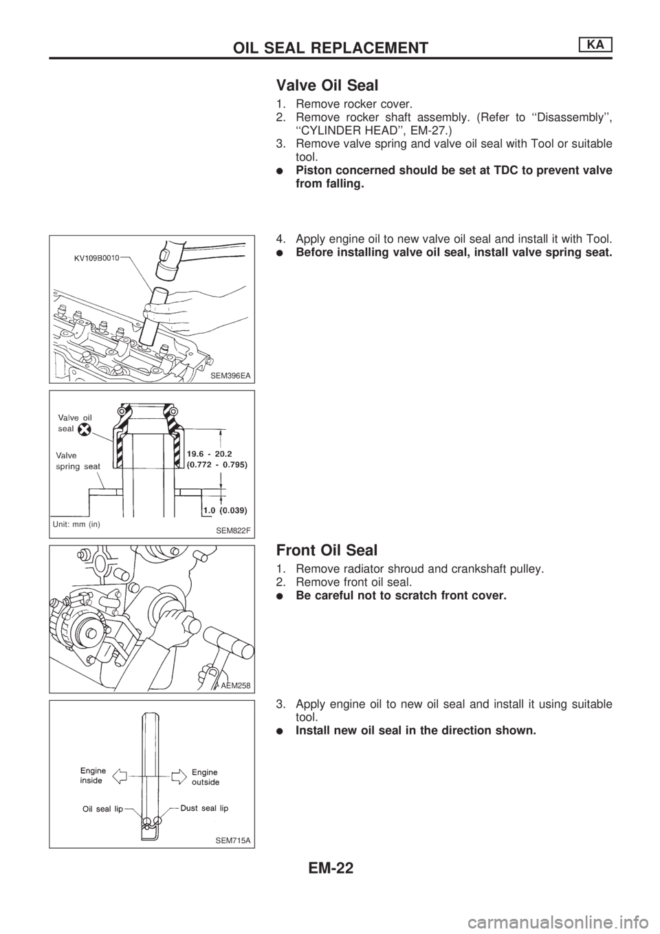
Valve Oil Seal
1. Remove rocker cover.
2. Remove rocker shaft assembly. (Refer to ``Disassembly'',
``CYLINDER HEAD'', EM-27.)
3. Remove valve spring and valve oil seal with Tool or suitable
tool.
lPiston concerned should be set at TDC to prevent valve
from falling.
4. Apply engine oil to new valve oil seal and install it with Tool.
lBefore installing valve oil seal, install valve spring seat.
Front Oil Seal
1. Remove radiator shroud and crankshaft pulley.
2. Remove front oil seal.
lBe careful not to scratch front cover.
3. Apply engine oil to new oil seal and install it using suitable
tool.
lInstall new oil seal in the direction shown.
SEM396EA
SEM822F
.Unit: mm (in)
AEM258
SEM715A
OIL SEAL REPLACEMENTKA
EM-22
Page 668 of 1659
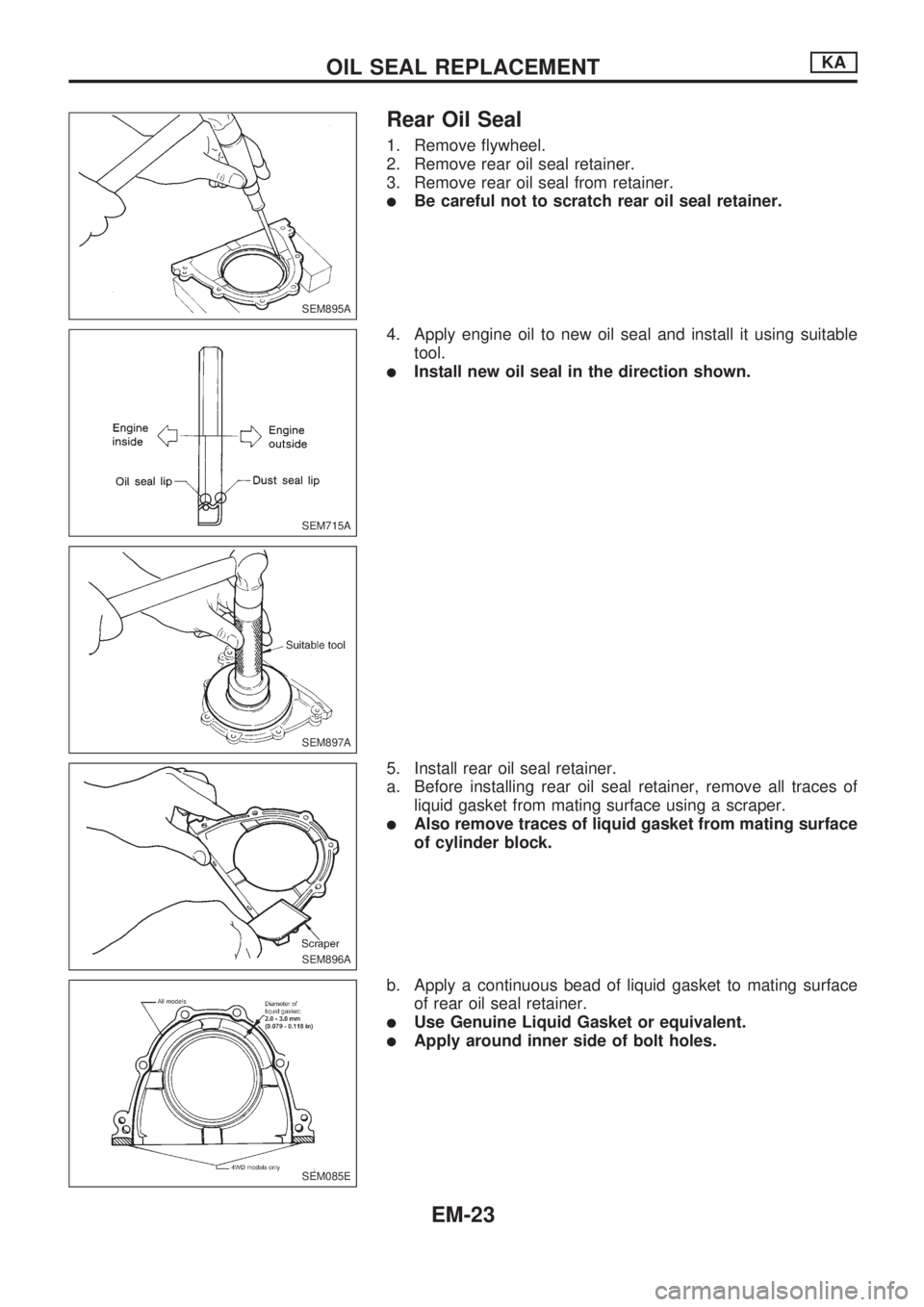
Rear Oil Seal
1. Remove flywheel.
2. Remove rear oil seal retainer.
3. Remove rear oil seal from retainer.
lBe careful not to scratch rear oil seal retainer.
4. Apply engine oil to new oil seal and install it using suitable
tool.
lInstall new oil seal in the direction shown.
5. Install rear oil seal retainer.
a. Before installing rear oil seal retainer, remove all traces of
liquid gasket from mating surface using a scraper.
lAlso remove traces of liquid gasket from mating surface
of cylinder block.
b. Apply a continuous bead of liquid gasket to mating surface
of rear oil seal retainer.
lUse Genuine Liquid Gasket or equivalent.
lApply around inner side of bolt holes.
SEM895A
SEM715A
SEM897A
SEM896A
SEM085E
OIL SEAL REPLACEMENTKA
EM-23
Page 669 of 1659
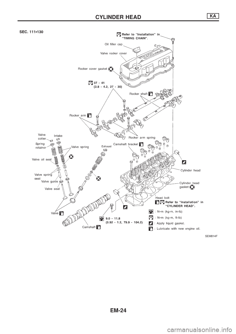
SEM814F
CYLINDER HEADKA
EM-24
Page 670 of 1659
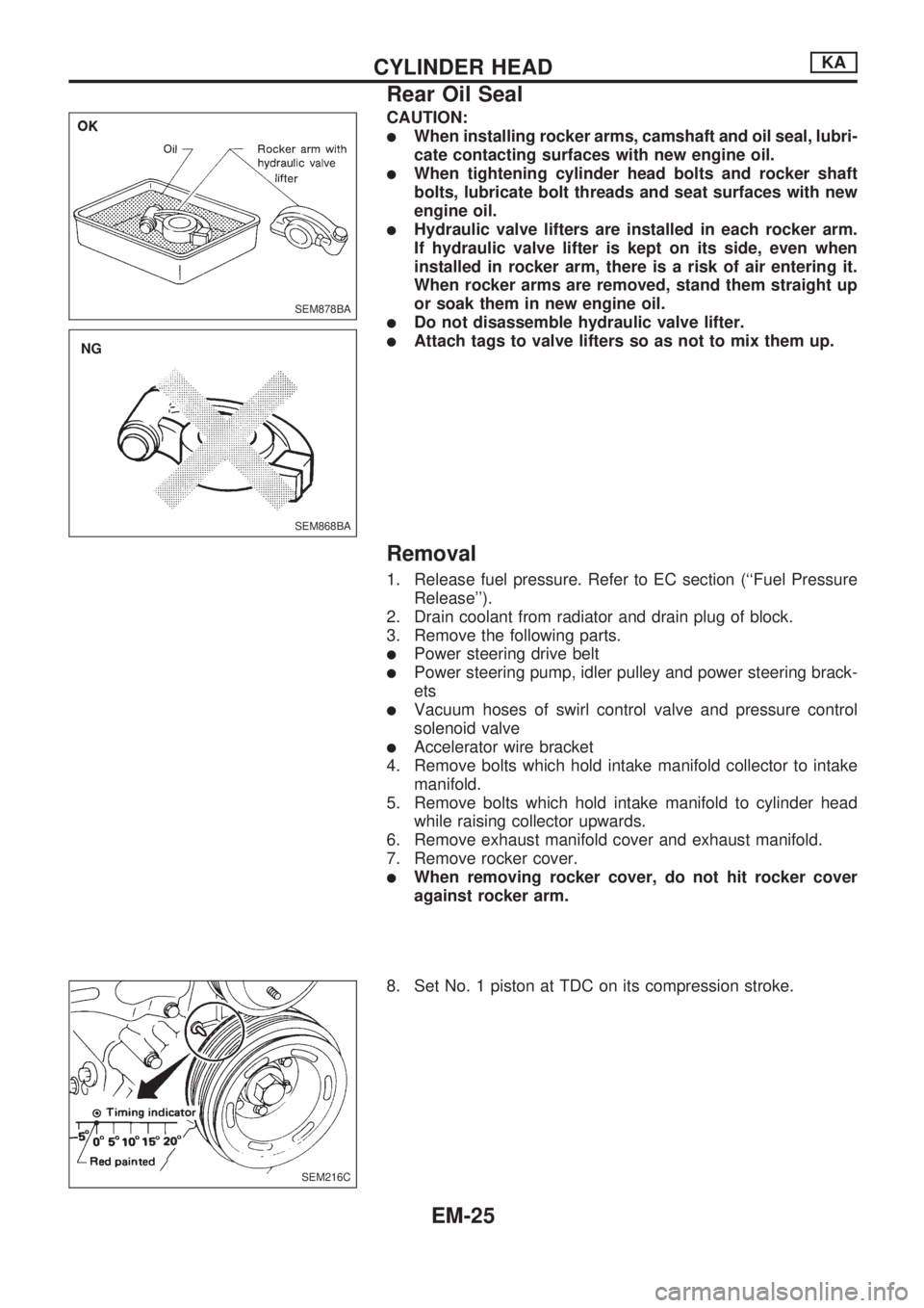
CAUTION:
lWhen installing rocker arms, camshaft and oil seal, lubri-
cate contacting surfaces with new engine oil.
lWhen tightening cylinder head bolts and rocker shaft
bolts, lubricate bolt threads and seat surfaces with new
engine oil.
lHydraulic valve lifters are installed in each rocker arm.
If hydraulic valve lifter is kept on its side, even when
installed in rocker arm, there is a risk of air entering it.
When rocker arms are removed, stand them straight up
or soak them in new engine oil.
lDo not disassemble hydraulic valve lifter.
lAttach tags to valve lifters so as not to mix them up.
Removal
1. Release fuel pressure. Refer to EC section (``Fuel Pressure
Release'').
2. Drain coolant from radiator and drain plug of block.
3. Remove the following parts.
lPower steering drive belt
lPower steering pump, idler pulley and power steering brack-
ets
lVacuum hoses of swirl control valve and pressure control
solenoid valve
lAccelerator wire bracket
4. Remove bolts which hold intake manifold collector to intake
manifold.
5. Remove bolts which hold intake manifold to cylinder head
while raising collector upwards.
6. Remove exhaust manifold cover and exhaust manifold.
7. Remove rocker cover.
lWhen removing rocker cover, do not hit rocker cover
against rocker arm.
8. Set No. 1 piston at TDC on its compression stroke.
SEM878BA
SEM868BA
.NG
SEM216C
CYLINDER HEADKA
Rear Oil Seal
EM-25