PONTIAC FIERO 1988 Service Repair Manual
Manufacturer: PONTIAC, Model Year: 1988, Model line: FIERO, Model: PONTIAC FIERO 1988Pages: 1825, PDF Size: 99.44 MB
Page 291 of 1825
4B-18 REAR AXLE
tire wear patterns. One indication of this condition is
"swerving on acceleration." If swerving on
acceleration is encountered, check the rear wheels for
different tire size, air pressure, or excessively different
wear patterns, and tread depths, before proceeding into
an overhaul operation.
Checking Limited-Slip Operation
1. Place transmisison
in Park position.
2. Raise
rear of vehicle until wheels are off the
ground, remove one wheel and tire assembly.
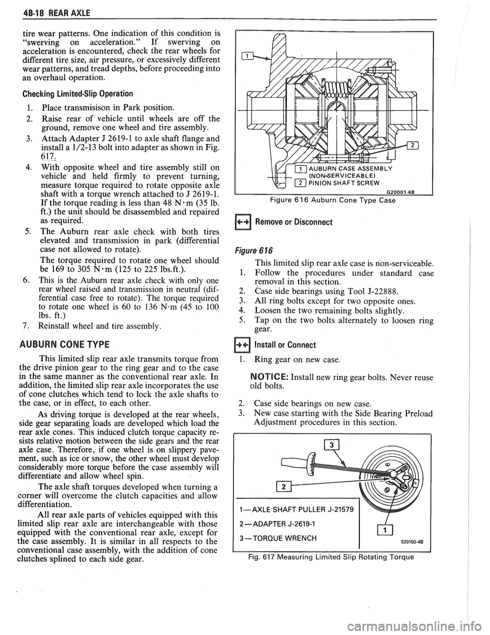
3. Attach Adapter J 2619-1 to axle shaft flange and
install a 1/2-13 bolt into adapter as shown in Fig.
617,
4. With opposite wheel and tire assembly still on
vehicle and held firmly to prevent turning,
measure torque required to rotate opposite axle
shaft with a torque wrench attached to J 2619-1.
If the torque reading is less than 48
N.m (35 lb.
ft.) the unit should be disassembled and repaired
as required.
5. The Auburn rear axle check with both tires
elevated and transmission in park (differential
case not allowed to rotate).
The torque required to rotate one wheel should
be 169 to 305
N-m (125 to 225 1bs.ft.).
6. This is the Auburn rear axle check with only one
rear wheel raised and transmission in neutral (dif-
ferential case free to rotate). The torque required
to rotate one wheel is
60 to 136 N-m (45 to 100
lbs. ft.)
7. Reinstall wheel and tire assembly.
AUBURN CONE TYPE
This limited slip rear axle transmits torque from
the drive pinion gear to the ring gear and to the case
in the same manner as the conventional rear axle. In
addition, the limited slip rear axle incorporates the use
of cone clutches which tend to lock the axle shafts to
the case, or in effect, to each other.
As driving torque is developed at the rear wheels,
side gear separating loads are developed which load the
rear axle cones. This induced clutch torque capacity re-
sists relative motion between the side gears and the rear
axle case. Therefore, if one wheel is on slippery pave-
ment, such as ice or snow, the other wheel must develop
considerably more torque before the case assembly will
differentiate and allow wheel spin.
The axle shaft torques developed when turning a
corner will overcome the clutch capacities and allow
differentiation.
All rear axle parts of vehicles equipped with this
limited slip rear axle are interchangeable with those
equipped with the conventional rear axle, except for
the case assembly. It is similar in all respects to the
conventional case assembly, with the addition of cone
clutches splined to each side gear.
INOWERVICEABLE) PINION SHAFT SCREW
Figure 6 16 Auburn Cone Type Case
Remove or Disconnect
Figure 6 16
This limited slip rear axle case is non-serviceable,
1. Follow the procedures under standard case
removal in this section.
2. Case side bearings using Tool J-22888.
3. All ring bolts except for two opposite ones.
4. Loosen the two remaining bolts slightly.
5. Tap on the two bolts alternately to loosen ring
gear.
Install or Connect
1.
Ring gear on new case.
NOTICE: Install new ring gear bolts. Never reuse
old bolts.
2. Case side bearings on new case.
3. New case starting with the Side Bearing Preload
Adjustment procedures in this section.
1 -AXLE SHAFT PULLER J-21579
2
-ADAPTER J-2619-1
3-TORQUE WRENCH
Fig.
617 Measuring Limited Slip Rotating Torque
Page 292 of 1825
REAR AXLE 48-19
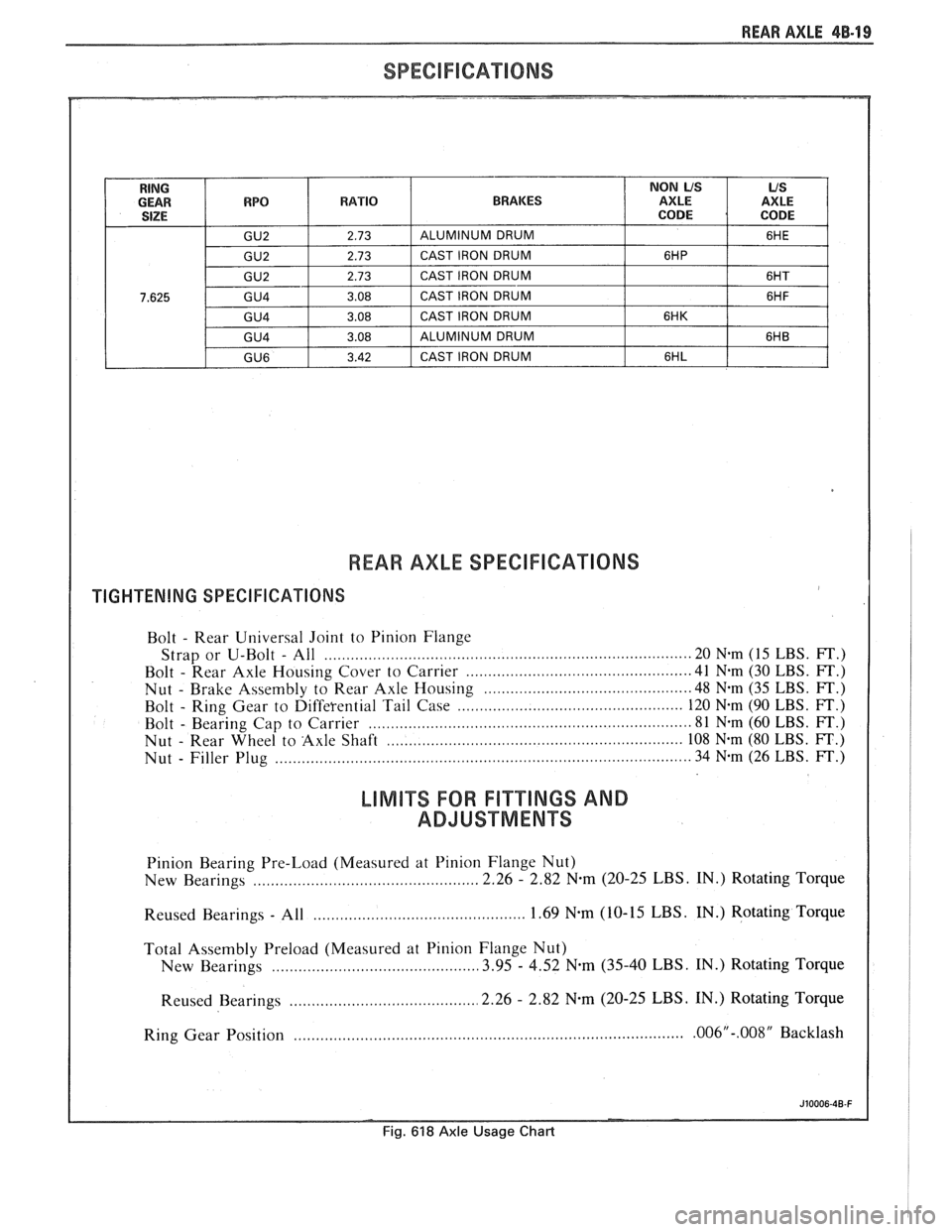
RING NON US US GEAR WPQ RATIO BRAKES AXLE AXLE SIZE CODE CODE
GU2 2.73 ALUMINUM DRUM
6HE
GU2 2.73 CAST IRON DRUM 6HP
GU2 2.73 CAST IRON DRUM
6HT
7.625 G U4 3.08 CAST IRON DRUM 6HF
GU4 3.08 CAST IRON DRUM 6HK
G U4 3.08 ALUMINUM DRUM 6HB
GU6 3.42 CAST IRON DRUM 6HL
REAR AXLE SPEClFICAnONS
TIGHTENING SPECIFICATIONS
Bolt - Rear
Universal Joint to Pinion Flange
Strap or U-Bolt
- All ................................................................................ 20 Nem (15 LBS. FT.)
Bolt
- Rear Axle Housing Cover to Carrier ........................................... 41 N.m (30 LBS. FT.)
Nut
- Brake Assembly to Rear Axle Housing .......................................... 48 N-m (35 LBS. FT.)
Bolt
- Ring Gear to Differential Tail Case ............................................. 120 N.m (90 LBS. FT.)
Bolt
- Bearing Cap to Carrier ....................................................................... 81 N-m (60 LBS. FT.)
Nut
- Rear Wheel to Axle Shaft .................................................................. 108 N-m (80 LBS. FT.)
Nut
- Filler Plug ............................................................................................. 34 N-m (26 LBS. FT.)
LlMlTS FOR FI"TTINGS AND
ADJUSTMENTS
Pinion Bearing Pre-Load (Measured at Pinion Flange Nut)
New Bearings
................................................... 2.26 - 2.82 N-m (20-25 LBS. IN.) Rotating Torque
............................................. Reused Bearings - All 1.69 N-m (10-
15 LBS. IN.) Rotating Torque
Total Assembly Preload (Measured at Pinion Flange Nut)
New Bearings
.......................................... 3.95 - 4.52 N.m (35-40 LBS. IN.) Rotating Torque
.......................................... Reused Bearings 2.26 - 2.82 N.m (20-25 LBS. IN.)
Rotating Torque
Ring Gear Position
........................................................................................ .006"-.008" Backlash
Fig. 618 Axle Usage Chart
Page 293 of 1825
dB-20 RWR AXLE
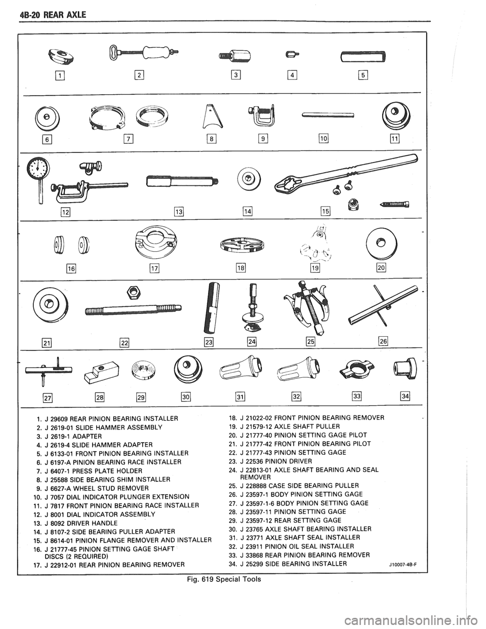
1. J 29609 REAR PINION BEARING INSTALLER 18. J 21022-02
FRONT PINION BEARING REMOVER
2.
J 2619-01 SLIDE HAMMER ASSEMBLY 19. J 21579-12 AXLE
SHAFT PULLER
3.
J 2619-1 ADAPTER 20. J 21777-40 PINION
SETING GAGE PILOT
I 4.J2619-4SLlDEHAMMERADAPTER 21. J 21777-42 FRONT PINION BEARING PILOT
5. J 6133-01 FRONT PINION BEARING INSTALLER 22. J 21777-43
PINION SETTING GAGE
6. J 6197-A PINION BEARING RACE INSTALLER 23. J 22536
PINION DRIVER
7.
J 6407-1 PRESS PLATE HOLDER 24. J 22813-01 AXLE
SHAFT BEARING AND SEAL
8.
J 25588 SlDE BEARING SHIM INSTALLER REMOVER
9.
J 6627-A WHEEL STUD REMOVER 25. J 228888
CASE SlDE BEARING PULLER
10.
J 7057 DlAL INDICATOR PLUNGER EXTENSION 26. J 23597-1 BODY
PlNlON SETTING GAGE
11.
J 7817 FRONT PlNlON BEARING RACE INSTALLER 27. J 23597-1-6
BODY PlNlON SETING GAGE
12.
J 8001 DlAL INDICATOR ASSEMBLY 28. J 23597-11
PlNlON SETING GAGE
13.
J 8092 DRIVER HANDLE 29. J 23597-12
REAR SETTING GAGE
14.
J 8107-2 SlDE BEARING PULLER ADAPTER 30. J 23765 AXLE SHAFT BEARING
INSTALLER
15.
J 8614-01 PINION FLANGE REMOVER AND INSTALLER 31. 23771 AXLE SHAFT SEAL INSTALLER
16.
J 21777-45 PlNlON SETTING GAGE SHAFT 32. J 2391
1 PlNlON OIL SEAL INSTALLER
DISCS (2 REQUIRED) 33. J 33868
REAR PINION BEARING REMOVER
17.
J 22912-01 REAR PINION BEARING REMOVER 34. J 25299 SIDE BEARING
INSTALLER ~10007-40-F
Fig. 619 Special Tools
Page 294 of 1825
BRAKES
NOTICE: All brake attaching fasteners are important attaching parts in that they could affect the performance of vital parts
and systems.
andlor could result in major repair expense . They must be replaced with one of the same part number or with an
equivalent part if replacement becomes necessary
. Do not use a replacement part of lesser quality or substitute design .
Torque values must be used as specified during reassembly to assure proper retention of parts .
CAUTION: When servicing brake parts. do not create dust by grinding. sanding brake linings. or by cleaning brake
parts with a dry brush or with compressed air
. Many brake parts contain asbestos fibers which can become airborne if
dust is created during servicing
. Breathing dust containing asbestos fibers may cause serious bodily harm . A water
dampened cloth or water based solution should be used to remove any dust on brake parts
. Equipment is commer-
cially available to perform this washing function
. These wet methods will prevent asbestos fibers from becoming
airborne
.
CONTENTS
......................... General Description 5.2
Composite Master Cylinder
.................. 5.2
Brake Fluid Level
lndicatgr ................... 5.2
Operation of Disc Brake
..................... 5.2
Operation of Drum Brake
.................... 5.2
Operation of Combination Valve
............... 5.2
Brake Pressure Differential
.......................... Warning Switch 5.2
Diagnosis and Inspection ..................... 5.3
Brake System Testing
....................... 5.3
External Conditions That Affect Brake Performance
.................... -5-3
Warning Lamp Operation .................... 5.3
Brake Fluid Leaks
.......................... 5.3
Master Cylinder Check
...................... 5.3
Substandard or Contaminated
BrakeFluid ............................. 5-3
............................. On-Car Service 5.7
Brake Pedal Replacement
................... 5.7
Stoplamp Switch Adjustment ................. 5-7
Filling Master Cylinder Reservoirs
............. 5-7
Bleeding Brake Hydraulic System
............. 5.7
Manual Bleeding
......................... 5.8
Pressure Bleeding
........................ 5.8
Flushing Brake Hydraulic System
............. 5.9
Brake Pipe Replacement
.................... 5.9
............................. I.S.O. Flare 5.9
Brake Hose Inspection
...................... 5.9
Brake Hose Replacement
.................... 5.11
Front Brake Hose
........................ 5.11
....................... Center Brake Hose 5.12
..................... Rear Disc Brake Hose 5.12
ParkingBrake ............................. 5-13
Parking Brake Control Assembly
.............. 5.13 Parking Brake Cables
....................... 5.14
Parking Brake Front Cable
................. 5.14
Parking Brake Rear Cable (Drum Brakes)
..... 5.14
Parking Brake Rear Cable (Disc Brakes)
...... 5.15
Brake Lining Inspection
..................... 5.15
............. Inspecting and Refinishing Rotors 5-15
Thickness
Variat~on Check ................. 5.15
Lateral
Runout Check ..................... 5.15
Rotor Tolerance and Surface Finish
.......... 5.16
Refinishing Brake Rotors
.................. 5-16
lnspecting and Refinishing Brake
Drums
................................. 5-16
Cracked Scored, or Grooved Drum
.......... 5.16
Out-of-Round or Tapered Drum
............. 5.16
Refinishing Brake Drums
.................. 5.16
Brake Drum Balance
..................... -5-16
Combination Valve ......................... 5.17
Testing Combination Valve Electrical
............................... Circuit 5.17
Testing Combination Valve Warning
.......................... Lamp Switch 5.17
.......... Combination Valve Replacement 5.17
............ Power Brake Vacuum Hose Filter 5.17
Unit Repair
................ Composite Master Cylinder .5A 3.1
Disc Brake Caliper Assembly
....................... 300013100 Series 581 -1
Disc Brake Caliper Assembly
3548 Series
........................... .5B 6.1
........ Direct Torque Drum Brake Assembly .5C 3.1
Power Head Assembly
-
.................... Tandem Diaphragm .5D 2.1
.............. Specifications and Special Tools 5F-1
Page 295 of 1825
5-2 BRAKES
GENERAL DESCRIPTION
COMPOSIE EASTER CYLINDER
This vehicle uses a composite master cylinder which has
an aluminum body and a clear nylon reservoir with fluid
level indicators. The master cylinder uses a "quick take-up" feature in the
rear chamber to reduce pedal travel which may result from
increased fluid displacement required to move the caliper
piston. The quick take-up master cylinder includes a spring
loaded ball check valve which holds pressure in the
large-
diameter rear chamber. When the brake is first applied, the
movement of the rear piston causes fluid to be displaced
forward, past the primary piston primary seal and into the
primary high pressure chamber, which feeds the front
brakes. At a predetermined pressure, 480-690
kPa (70-100
mi), the ball unseats and fluid from the largi! rear bore is
disblaced past the ball and into the reservoir. The primary
and secondary high pressure chambers supply pressure to
the front and rear brakes, respectively, in the usual way.
When the pedal is released, the large-bore chamber is filled
with fluid by drawing fluid from the reservoir around the
quick take-up lip seal, and also through a small orifice in the
ball seat.
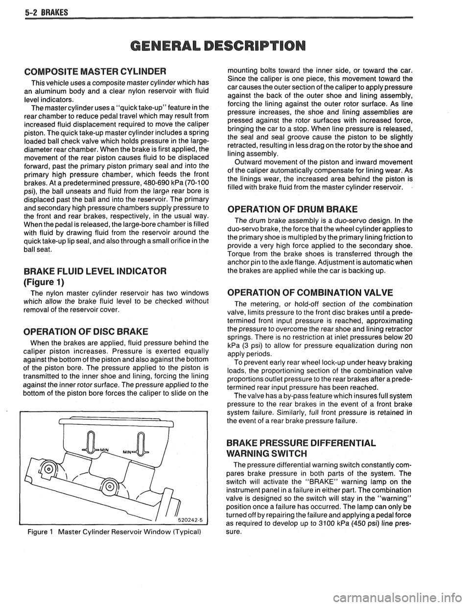
BRAKE FLUID LEVEL INDICATOR
(Figure 1)
The nylon master cylinder reservoir has two windows
which allow the brake fluid level to be checked without
removal of the reservoir cover.
OPERATION OF DISC BRAKE
When the brakes are applied, fluid pressure behind the
caliper piston increases. Pressure is exerted equally
against the bottom of the piston and also against the bottom
of the piston bore. The pressure applied to the piston is
transmitted to the inner shoe and lining, forcing the lining
against the inner rotor surface. The pressure applied to the
bottom of the piston bore forces the caliper to slide on the
Figure
1 Master Cylinder Reservoir Window (Typical) mounting bolts toward the inner side,
or toward the car.
Since the caliper is one piece, this movement toward the
car causes the outer section of the caliper to apply pressure
against the back of the outer shoe and lining assembly,
forcing the lining against the outer rotor surface. As line
pressure increases, the shoe and lining assemblies are
pressed against the rotor surfaces with increased force,
bringing the car to a stop. When line pressure is released,
the seal and seal groove cause the piston to be slightly
retracted, resulting in less drag on the rotor by the shoe and
lining assembly.
Outward movement of the piston and inward movement
of the caliper automatically compensate for lining wear. As
the linings wear, the increased area behind the piston is
filled with brake fluid from the master cylinder reservoir.
OPERATION OF DRUM BRAKE
The drum brake assembly is a duo-servo design. In the
duo-servo brake, the force that the wheel cylinder applies to
the primary shoe is
multipled by the primary lining friction to
provide a very high force applied to the secondary shoe.
Torque from the brake shoes is transferred through the anchor pin to the axle flange. Adjustment is automatic when
the brakes are applied while the car is backing up.
OPERATION OF COMBINATION VALVE
The metering, or hold-off section of the combination
valve, limits pressure to the front disc brakes until a prede-
termined front input pressure is reached, approximating
the pressure to overcome the rear shoe and lining retractor
springs. There is no restriction at inlet pressures below 20
kPa (3 psi) to allow for pressure equalization during non
apply periods.
To prevent early rear wheel lock-up under heavy braking
loads, the proportioning section of the combination valve
proportions outlet pressure to the rear brakes after a prede-
termined rear input pressure has been reached.
The valve has a by-pass feature which insures full system
pressure to the rear brakes in the event of a front brake
system failure. Similarly, full front pressure is retained in
the event of a rear brake pressure failure.
BRAKE PRESSURE DIFFERENTIAL
WARNING
SWITCH
The pressure differential warning switch constantly com-
pares brake pressure in both parts of the system. The
switch will activate the "BRAKE" warning lamp on the
instrument panel in a failure in either part. The combination
valve is designed so the switch will stay in the "warning"
position once a failure has occurred. The lamp can only be
turned off by repairing the failure and applying a pedal force
as required to develop up to 3100
kPa (450 psi) line pres-
sure.
Page 296 of 1825
BRAKES 5-3
DIAGNOSIS AND INSPECTION
BRAKE SYSTEM TESTING
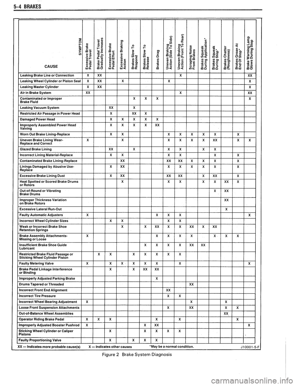
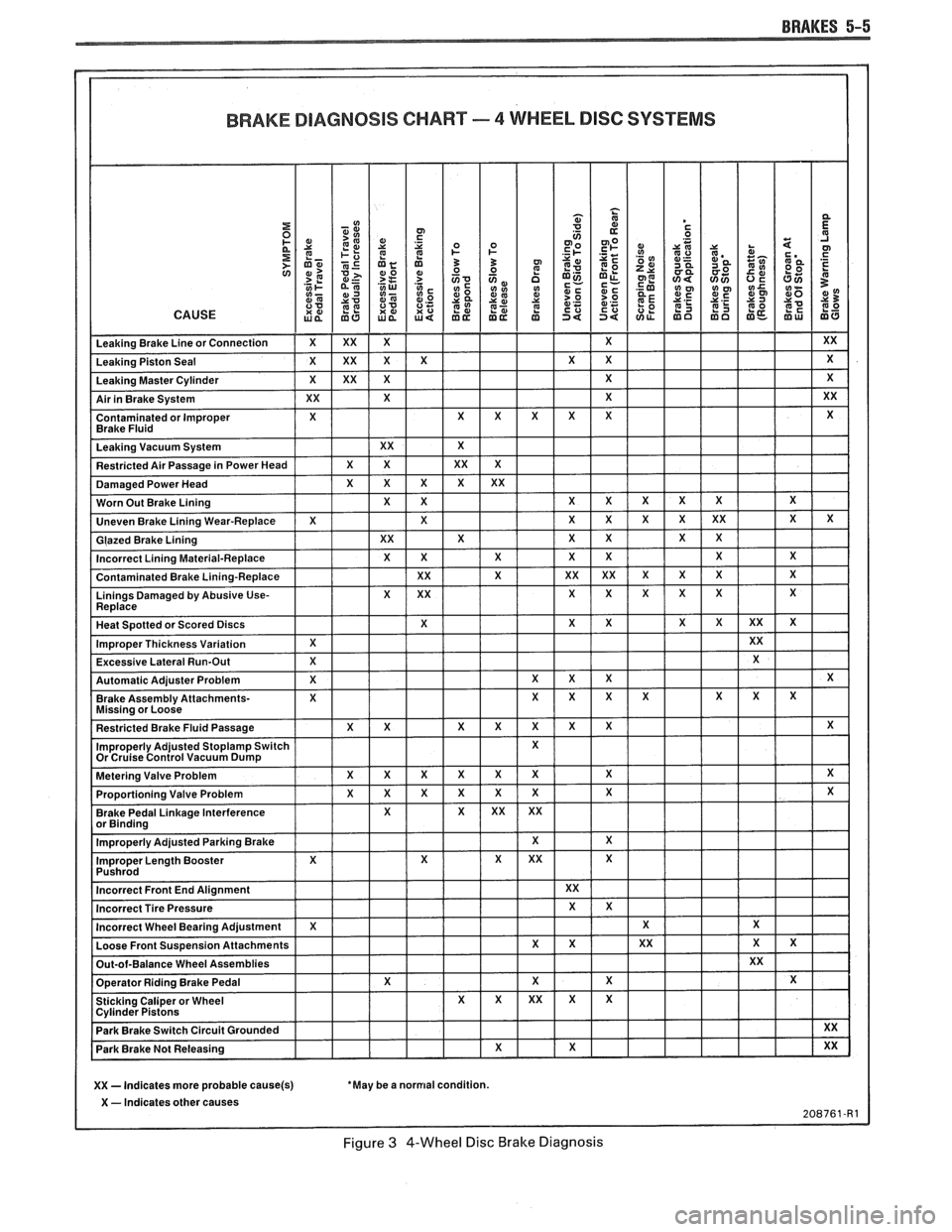
(Figures
2 through 4)
Brakes should be tested on dry, clean, reasonably
smooth and level roadway. A true test of brake performance
cannot be made if the roadway is wet, greasy or covered
with loose dirt so that all tires do not grip the road equally.
Testing will also be affected if the roadway is crowned
which would throw the weight of the car toward the wheels
on one side. If the roadway is too rough, the wheels will tend
to bounce. Test brakes at different car speeds with both light and
heavy pedal pressure, avoid locking the brakes and sliding
the tires. Locked brakes and sliding tires do not indicate
brake efficiency, because heavily braked, but turning
wheels will stop the car in less distance than locked brakes.
More tire-to-road friction is present with a heavily braked
turning tire than with a sliding tire. The brake system is designed and balanced to avoid
locking the wheels, except at very high deceleration levels.
The shortest stopping distance and best control is achieved
without brake lock-up.
Because of high deceleration capability, a firmer pedal
may be felt at higher deceleration levels.
External Conditions That Affect Brake Performance
1. Tires. Tires having unequal contact and grip on road
will cause unequal braking. Tires must be equally
inflated and tread pattern of right and left tires must
be approximately equal.
2. Car Loading. A heavily loaded car requires more
braking effort. When a car has unequal loading, the
most heavily loaded wheels require more braking
power than others.
3. Wheel Alignment. Misalignment of the wheels, par-
ticularly excessive camber and caster, will cause the
brakes to pull to one side.
4. Front Wheel Bearings. A loose front wheel bearing
BRAKE FLUID LEAKS
With engine running at idle and the transmission in neu-
tral, depress the brake pedal and hold a constant foot pres-
sure.
If the pedal gradually falls away with the constant
pressure, the hydraulic system may be leaking. Perform a
visual check to confirm any suspected leak.
Check the master cylinder fluid levels. While a slight drop
in reservoir level does result from normal lining wear, an
abnormally low level in either reservoir indicates
a leak in
the system. The hydraulic system may be leaking either
internally or externally. See "Master Cylinder Check."
Also, the system may appear to pass this test but still have
slight leakage.
If fluid levels are normal, check the vacuum booster
pushrod length. If an incorrect length pushrod is found,
adjust or replace the
pushrod. Check the service brake
pedal travel and the parking brake adjustment.
When checking the fluid levels, the master cylinder reser-
voir may be as low as
25 mm (1 inch) from the top if the front
linings are worn. This is not abnormal.
MASTER CYLINDER CHECK
These checks will help locate some master cylinder mal-
functions. Use the Brake Diagnosis Charts to help isolate
the problem if it is not found by using these tests.
1. Check for a cracked master cylinder casting or brake
fluid around the master cylinder. Leaks are indicated
only if there is at least a drop of fluid. A damp condi-
tion is not abnormal.
2. Check for a binding pedal linkage.
3. Disassemble the master cylinder and check for swol-
len or stretched piston
seal(s). If swollen seals are
found, substandard or contaminated brake fluid
should be suspected.
If contaminated, all compo-
nents should be disassembled and cleaned. All rub-
ber components should be replaced and all the pipes
should be flushed.
permits the front wheel to tilt and lose contact with the
SUBSTANDARD OR CONTAMINATED brake shoe linings causing erratic brake operation. BRAKE FLUID
WARNING LAMP OPERATION
The brake system uses a single red "BRAKE" warning
lamp located in the instrument panel cluster. When the
ignition switch is in the "START" position, the "BRAKE"
warning lamp should come on. It should go off when the
ignition switch returns to the "RUN" position.
The following conditions will activate the "BRAKE"
warning lamp:
1. Parking brake applied. The lamp should be on when
tfie parking brake is applied and the ignition switch is
"ON."
2. Pressure differential switch detects a failure. See
"Brake Pressure Differential Warning Switch" in this
section. Improper
brake fluid, mineral oil or water in the fluid may
cause the brake fluid to boil or the rubber components to
deteriorate.
If piston cups are swollen, the rubber parts have dete-
riorated. This deterioration may also be seen by swollen
wheel cylinder piston cups on the drum brake wheels or a
swollen master cylinder cover diaphragm.
If rubber deterioration is evident, disassemble all hydrau-
lic parts and wash with alcohol. Dry these parts with com-
pressed air before assembly to keep alcohol out of the
system. Replace all rubber parts in the system, including
hoses. Check for fluid on the linings. If excessive fluid is
found, replace the linings.
If master cylinder piston seals are satisfactory, check for
leakage or excessive heat conditions. If condition is not
found, drain fluid, flush with brake fluid, fill and bleed the
system.
Page 297 of 1825
5-4 BRAKES
Figure 2 Brake System Diagnosis
Page 298 of 1825
BRAKES 5-5
BRAKE DIAGNOSIS CHART - 4 WHEEL DISC SYSEEMS
XX - Indicates more probable cause(s) 'May be a normal condition.
X - Indicates other
Figure 3 4-Wheel Disc Brake Diagnosis
Page 299 of 1825
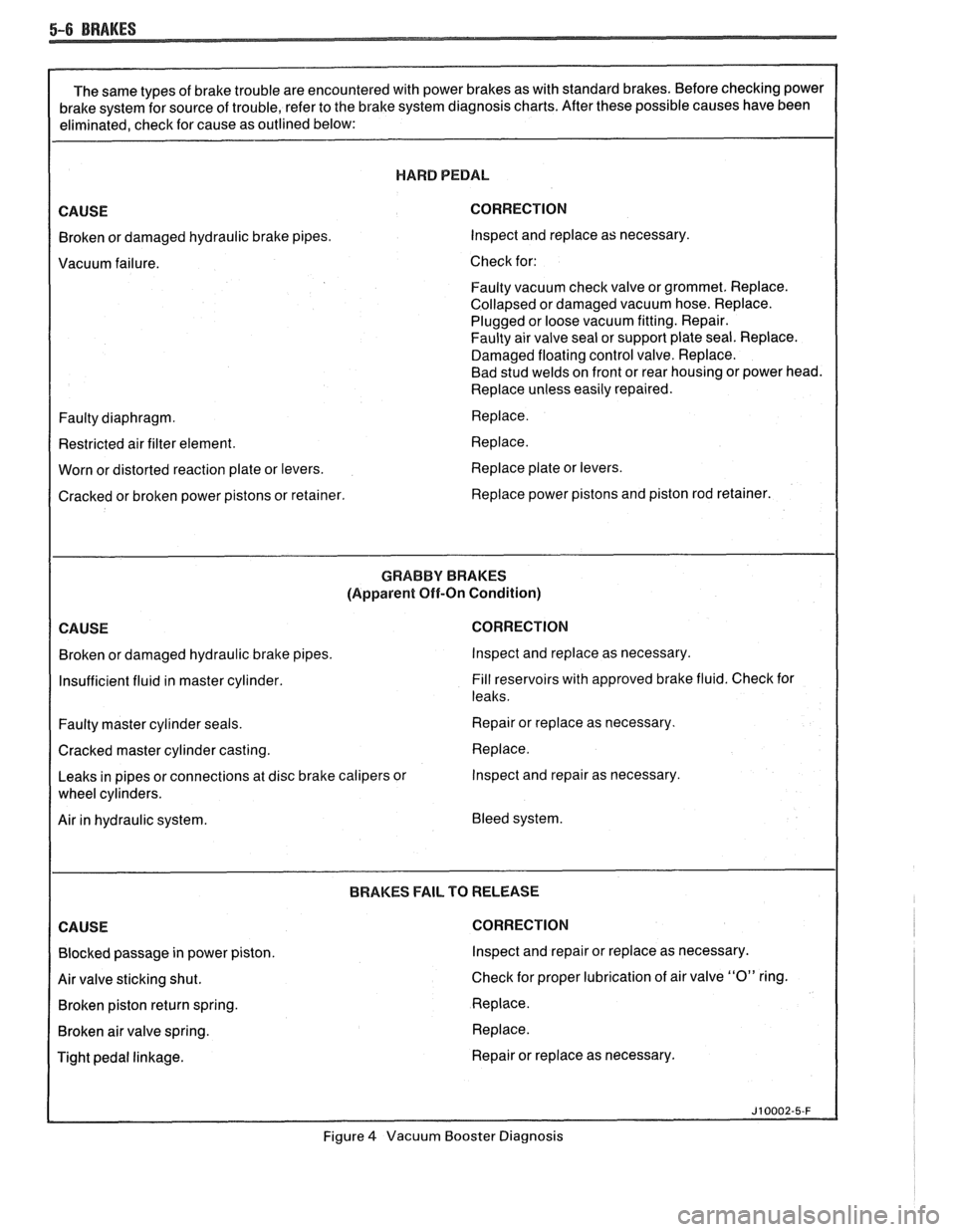
HARD PEDAL
CORRECTION
Broken or damaged hydraulic brake pipes. Inspect and replace
as necessary.
Vacuum failure. Check for:
Faulty vacuum check valve or grommet. Replace.
Collapsed or damaged vacuum hose. Replace.
Plugged or loose vacuum fitting. Repair.
Faulty air valve seal or support plate seal. Replace.
Damaged floating control valve. Replace.
Bad stud welds on front or rear housing or power head.
Replace unless easily repaired.
Faulty diaphragm. Replace.
Restricted air filter element. Replace.
Worn or distorted reaction plate or levers. Replace
plate or levers.
Cracked or broken power pistons or retainer. Replace power pistons and piston
rod retainer.
GRABBV BRAKES
(Apparent Off-On Condition)
CORRECTION
Broken or damaged hydraulic brake pipes. Inspect and replace
as necessary.
Insufficient fluid in master cylinder. Fill
reservoirs with approved brake fluid. Check for
leaks.
Faulty master cylinder seals. Repair or replace
as necessary.
Cracked master cylinder casting. Replace.
Leaks in pipes or connections at disc brake calipers or Inspect and repair
as necessary.
Air in hydraulic system. Bleed system.
BRAKES
FAIL TO RELEASE CORRECTION
Blocked passage in power piston. Inspect and repair or replace
as necessary.
Air valve sticking shut. Check
for proper lubrication of air valve
"0" ring.
Broken piston return spring. Replace.
Broken air valve spring. Replace.
Tight pedal linkage. Repair or replace
as necessary.
Figure
4 Vacuum Booster Diagnosis
Page 300 of 1825
BRAKES 5-7
ONmCAR SERVICE
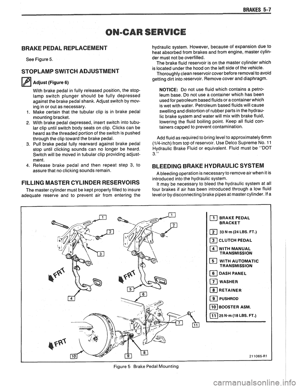
BRAKE PEDAL REPLACEMENT
See Figure 5.
STOPLAMP SWITCH ADJUSTMENT
Adjust (Figure 6)
With brake pedal in fully released position, the stop-
lamp switch plunger should be fully depressed
against the brake pedal shank. Adjust switch by mov-
ing in or out as necessary.
1. Make certain that the tubular clip is in brake pedal
mounting bracket.
2. With brake pedal depressed, insert switch into tubu-
lar clip until switch body seats on clip. Clicks can be
heard as the threaded portion of the switch is pushed
through the clip toward the brake pedal.
3. Pull brake pedal fully rearward against brake pedal
stop until clicking sounds can no longer be heard.
Switch will be moved in tubular clip providing adjust-
ment.
4. Release brake pedal and then repeat step 3, to
assure that no clicking sounds remain.
FILLING MASTER CYLINDER RESERVOIRS
The master cylinder must be kept properly filled to insure
adequate reserve and to prevent air from entering the hydraulic
system. However, because of expansion due to
heat absorbed from brakes and from engine, master cylin-
der must not be overfilled.
The brake fluid reservoir is on the master cylinder which
is located under the hood on the left side of the vehicle.
Thoroughly clean reservoir cover before removal to avoid
getting dirt into reservoir. Remove cover and diaphragm.
NOTICE: Do not use fluid which contains a petro-
leum base. Do not use a container which has been
used for petroleum based fluids or a container which
is wet with water. Petroleum based fluids will cause
swelling and distortion of rubber parts in the hydrau-
lic brake system and water will mix with brake fluid,
lowering the fluid boiling point. Keep all fluid con-
tainers capped to prevent contamination.
Add fluid as required to bring level to
approximately6mm
(114-inch) from top of reservoir. Use Delco Supreme No. 1 1
Hydraulic Brake Fluid or equivalent. Fluid must be "DOT
3."
BLEEDING BRAKE HYDRAULIC SYSTEM
A bleeding operation is necessary to remove air when it is
introduced into the hydraulic system. It may be necessary to bleed the hydraulic system at all
four brakes if air has been introduced through a low fluid
level or by disconnecting brake pipes at master cylinder. If a
Figure
5 Brake Pedal Mounting