RENAULT KANGOO 1997 KC / 1.G Sheet Metal Work Workshop Manual
KANGOO 1997 KC / 1.G
RENAULT
RENAULT
https://www.carmanualsonline.info/img/7/1735/w960_1735-0.png
RENAULT KANGOO 1997 KC / 1.G Sheet Metal Work Workshop Manual
Trending: radiator, jacking, air conditioning, brake, height adjustment, engine, jacking points
Page 111 of 255
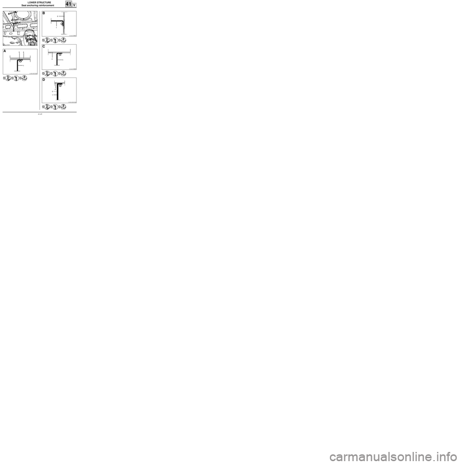
LOWER STRUCTURE
Seat anchoring reinforcement
41V
13222R
CAF11547-2R2
A4
1 3
CAA11538R7
B
3
1
CAA11538R5
C
4
1
CAN11690-3R4
D
4
1 2
41-69
Page 112 of 255
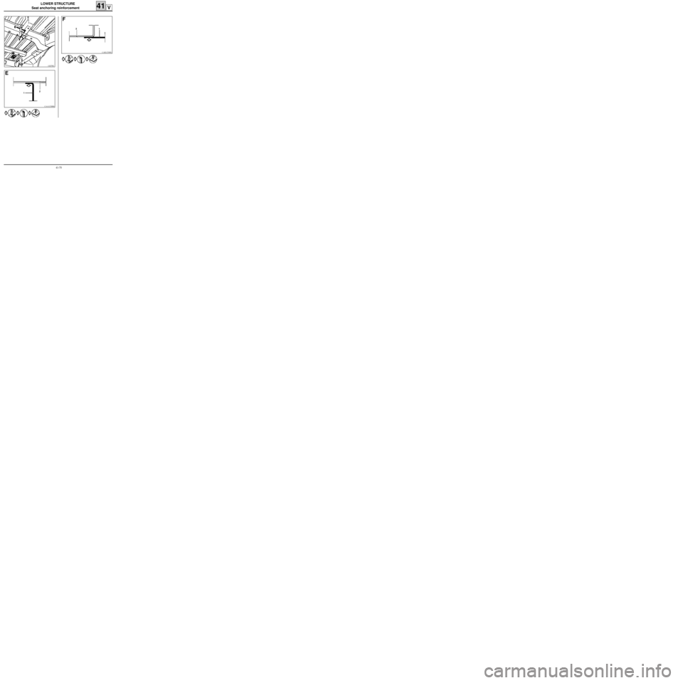
LOWER STRUCTURE
Seat anchoring reinforcement
41V
13237R2
CAA11538R6
E
12
CAR11700R1
F
1 2
41-70
Page 113 of 255
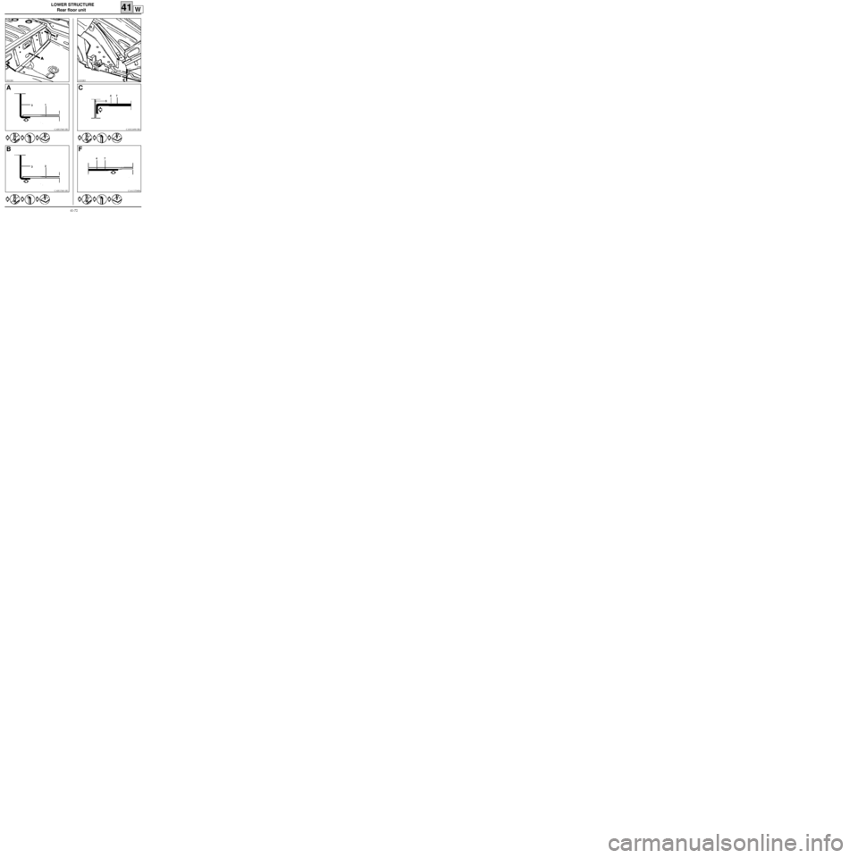
LOWER STRUCTURE
Rear floor unit
41W
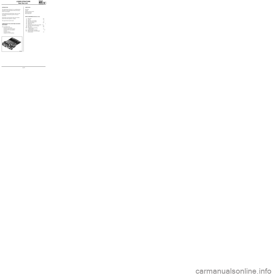
PRB4143
INTRODUCTION
The replacement of this part is a complementary
operation to the replacement of the rear end pa-
nel for a rear impact.
In the operation described below, there are only
descriptions of the joints specific to the part
concerned.
Information concerning the other parts will be
dealt with in the respective sections.
The repair bench must be used.
COMPOSITION OF THE PART FROM THE PARTS
DEPARTMENT
Part assembled with:
- rear end cross member,
- rear floor centre cross member,
- rear floor front cross member,
- rear floor,
- rear floor stiffener ,
- complete rear side members
JOINTS WITH:
Side floor
Tunnel
Sill panel closure panel
Side panel lining
Rear wheel arch
PARTS CONCERNED (thickness in mm):
1Side floor 0.8
2Tunnel 1.2
3Rear floor, rear section 1
4Sill panel closure panel 1.2
5Side panel lining 0.7
6Wheel arch 1
7Sill panel closure panel, rear section 1.5
8Rear floor front cross member 0.8
9Side panel 0.8
10Spring bumper mounting
reinforcement 1.5
11Spring bumper mounting 1.5
12Shock absorber mounting upper
reinforcement 1.2
41-71
Page 114 of 255
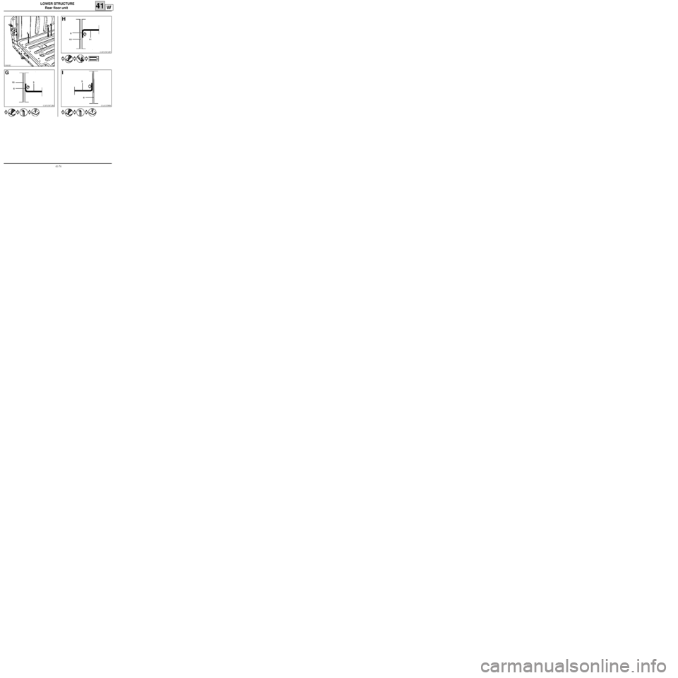
LOWER STRUCTURE
Rear floor unit
41W
13012R1
CAB11540-1R1
A
1
3
CAB11540-1R1
B
2
3
13232R3
CAN11690-3R1
C
54
CAA11536R6
F
477
41-72
Page 115 of 255
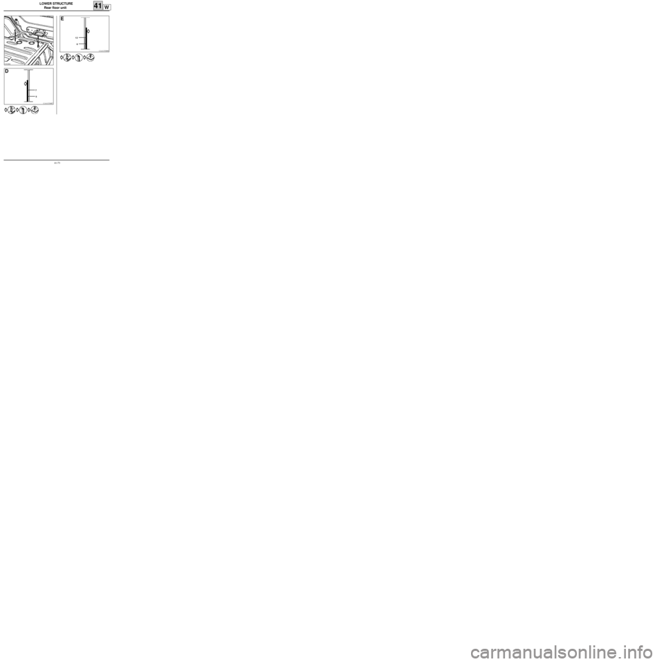
LOWER STRUCTURE
Rear floor unit
41W
13018R4
CAA11536R7
D
7
5
CAA11536R8
E
12
6
41-73
Page 116 of 255
LOWER STRUCTURE
Rear floor unit
41W
13001R2
CAF11547-2R4
G
3
6 10
CAF11547-2R7
H
6
11 10
CAA11538R4
I
3
6
41-74
Page 117 of 255
UPPER FRONT STRUCTURE
Front wing
INTRODUCTION
The replacement of this part is a basic operation for a frontal impact.
It is a removable bodywork component.
COMPOSITION OF THE PART FROM THE PARTS DEPARTMENT
Part assembled with:
- mudguard skirt,
- bumper mounting support .
42A
13330R
Remove :
- the plastic cover at (A) on the wing side (see section 55),
- the wheel arch plastic mudguards (see section 55),
- the bumper and its mounting blade (see section 55),
- the indicator repeater,
- the front wing : 8 hexagonal-head bolts Ø 6 mm and a torx bolt Ø 6 mm.
42-1
Page 118 of 255
UPPER FRONT STRUCTURE
Headlight carrier panel
42B
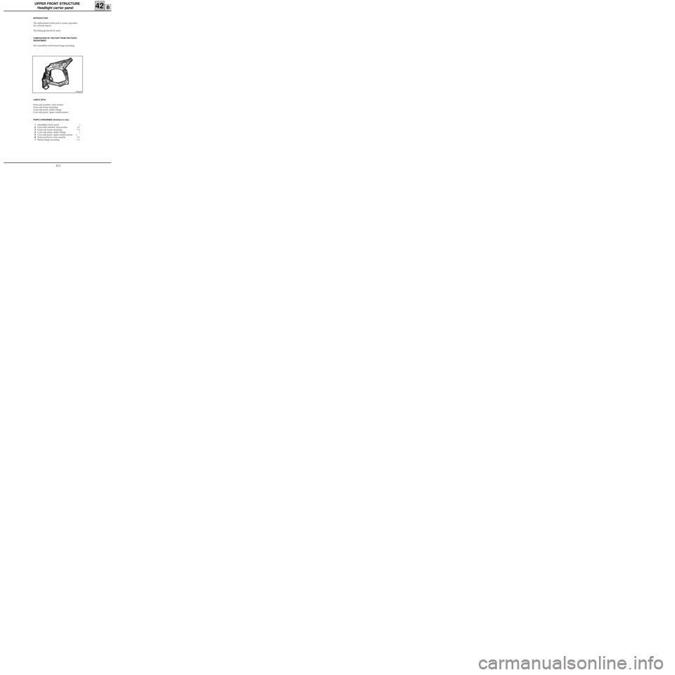
PRB4209
INTRODUCTION
The replacement of this part is a basic operation
for a frontal impact.
The fitting jig should be used.
COMPOSITION OF THE PART FROM THE PARTS
DEPARTMENT
Part assembled with bonnet hinge mounting.
JOINTS WITH:
Front side member, front section
Front sub-frame mounting
Cowl side panel (pillar lining)
Cowl side panel upper reinforcement
PARTS CONCERNED (thickness in mm):
1Headlight carrier panel 1
2Front side member, front section 1.5
3Front sub-frame mounting 1.5
4Cowl side panel (pillar lining) 1
5Cowl side panel upper reinforcement 1
6Front end lower cross member 1.5
7Bonnet hinge mounting 1.5
42-2
Page 119 of 255
UPPER FRONT STRUCTURE
Headlight carrier panel
42B
13002R
CAC11541-1R6
A
1 4
CAG11548R6
B
1 4 5
CAA11538-1R2
C
1 5
42-3
Page 120 of 255
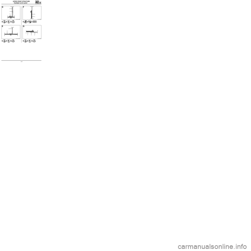
UPPER FRONT STRUCTURE
Headlight carrier panel
42B
CAN11690-2R8
D
1 4 5
CAA11538-1R1
E
14
CAA11536R7
F
7 3
CAP11696R6
G
6 12
42-4
Trending: mirror, air condition, diagram, wheel size, jack points, spare wheel, rear view mirror
