DODGE NEON 1999 Service Repair Manual
Manufacturer: DODGE, Model Year: 1999, Model line: NEON, Model: DODGE NEON 1999Pages: 1200, PDF Size: 35.29 MB
Page 111 of 1200
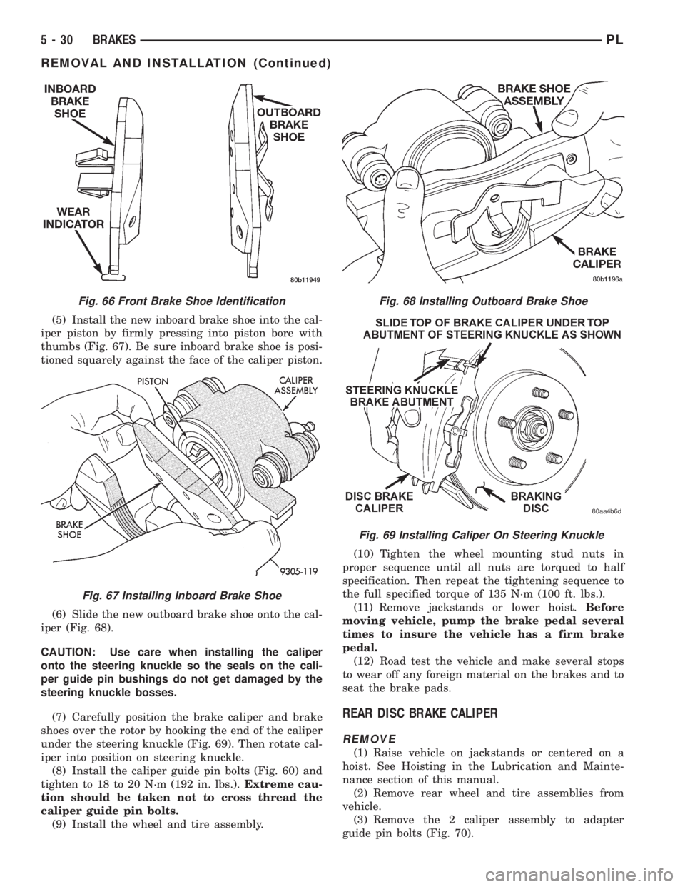
(5) Install the new inboard brake shoe into the cal-
iper piston by firmly pressing into piston bore with
thumbs (Fig. 67). Be sure inboard brake shoe is posi-
tioned squarely against the face of the caliper piston.
(6) Slide the new outboard brake shoe onto the cal-
iper (Fig. 68).
CAUTION: Use care when installing the caliper
onto the steering knuckle so the seals on the cali-
per guide pin bushings do not get damaged by the
steering knuckle bosses.
(7) Carefully position the brake caliper and brake
shoes over the rotor by hooking the end of the caliper
under the steering knuckle (Fig. 69). Then rotate cal-
iper into position on steering knuckle.
(8) Install the caliper guide pin bolts (Fig. 60) and
tighten to 18 to 20 N´m (192 in. lbs.).Extreme cau-
tion should be taken not to cross thread the
caliper guide pin bolts.
(9) Install the wheel and tire assembly.(10) Tighten the wheel mounting stud nuts in
proper sequence until all nuts are torqued to half
specification. Then repeat the tightening sequence to
the full specified torque of 135 N´m (100 ft. lbs.).
(11) Remove jackstands or lower hoist.Before
moving vehicle, pump the brake pedal several
times to insure the vehicle has a firm brake
pedal.
(12) Road test the vehicle and make several stops
to wear off any foreign material on the brakes and to
seat the brake pads.
REAR DISC BRAKE CALIPER
REMOVE
(1) Raise vehicle on jackstands or centered on a
hoist. See Hoisting in the Lubrication and Mainte-
nance section of this manual.
(2) Remove rear wheel and tire assemblies from
vehicle.
(3) Remove the 2 caliper assembly to adapter
guide pin bolts (Fig. 70).
Fig. 66 Front Brake Shoe Identification
Fig. 67 Installing Inboard Brake Shoe
Fig. 68 Installing Outboard Brake Shoe
Fig. 69 Installing Caliper On Steering Knuckle
5 - 30 BRAKESPL
REMOVAL AND INSTALLATION (Continued)
Page 112 of 1200
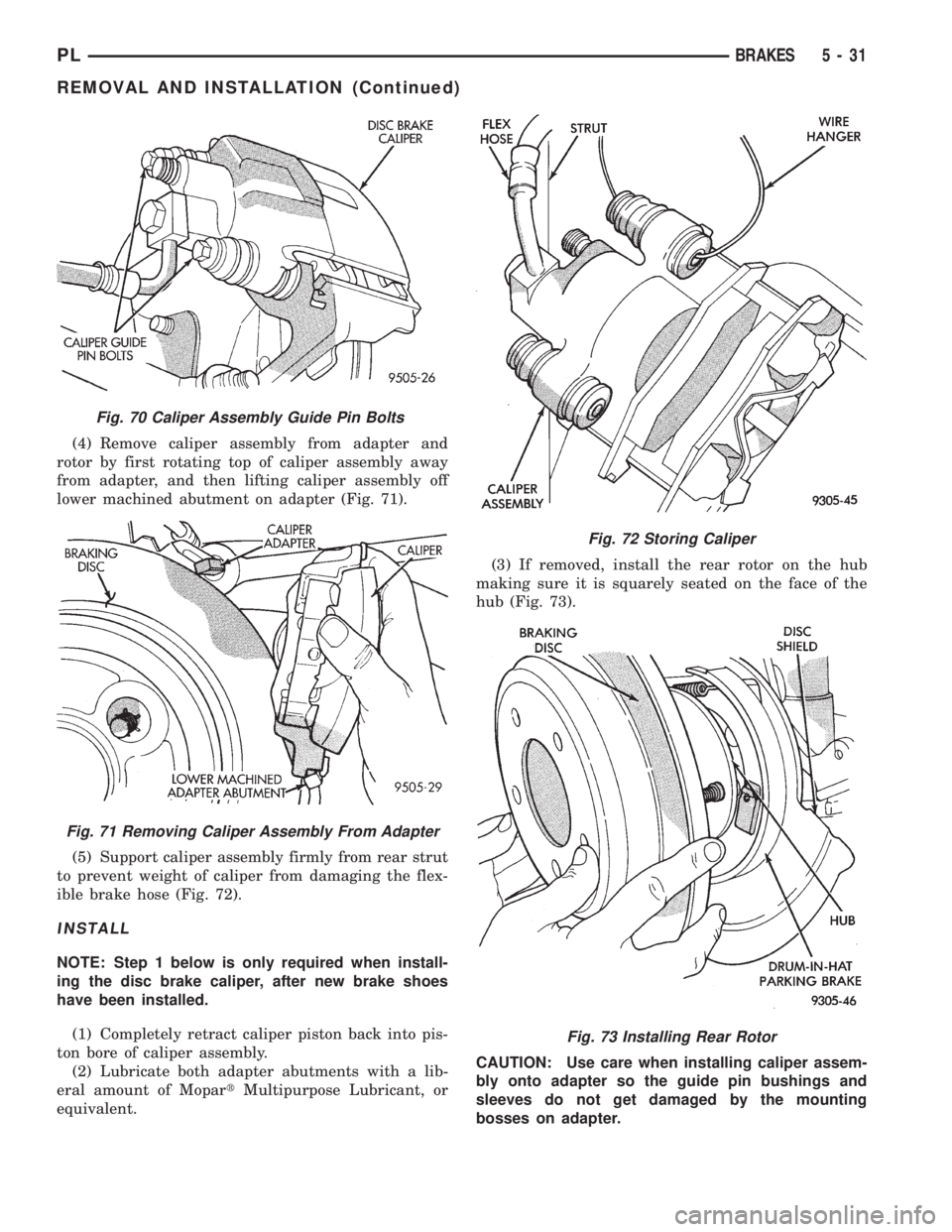
(4) Remove caliper assembly from adapter and
rotor by first rotating top of caliper assembly away
from adapter, and then lifting caliper assembly off
lower machined abutment on adapter (Fig. 71).
(5) Support caliper assembly firmly from rear strut
to prevent weight of caliper from damaging the flex-
ible brake hose (Fig. 72).
INSTALL
NOTE: Step 1 below is only required when install-
ing the disc brake caliper, after new brake shoes
have been installed.
(1) Completely retract caliper piston back into pis-
ton bore of caliper assembly.
(2) Lubricate both adapter abutments with a lib-
eral amount of MopartMultipurpose Lubricant, or
equivalent.(3) If removed, install the rear rotor on the hub
making sure it is squarely seated on the face of the
hub (Fig. 73).
CAUTION: Use care when installing caliper assem-
bly onto adapter so the guide pin bushings and
sleeves do not get damaged by the mounting
bosses on adapter.
Fig. 70 Caliper Assembly Guide Pin Bolts
Fig. 71 Removing Caliper Assembly From Adapter
Fig. 72 Storing Caliper
Fig. 73 Installing Rear Rotor
PLBRAKES 5 - 31
REMOVAL AND INSTALLATION (Continued)
Page 113 of 1200
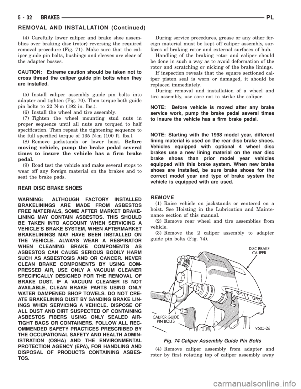
(4) Carefully lower caliper and brake shoe assem-
blies over braking disc (rotor) reversing the required
removal procedure (Fig. 71). Make sure that the cal-
iper guide pin bolts, bushings and sleeves are clear of
the adapter bosses.
CAUTION: Extreme caution should be taken not to
cross thread the caliper guide pin bolts when they
are installed.
(5) Install caliper assembly guide pin bolts into
adapter and tighten (Fig. 70). Then torque both guide
pin bolts to 22 N´m (192 in. lbs.).
(6) Install the wheel and tire assembly.
(7) Tighten the wheel mounting stud nuts in
proper sequence until all nuts are torqued to half
specification. Then repeat the tightening sequence to
the full specified torque of 135 N´m (100 ft. lbs.).
(8) Remove jackstands or lower hoist.Before
moving vehicle, pump the brake pedal several
times to insure the vehicle has a firm brake
pedal.
(9) Road test the vehicle and make several stops to
wear off any foreign material on the brakes and to
seat the brake pads.
REAR DISC BRAKE SHOES
WARNING: ALTHOUGH FACTORY INSTALLED
BRAKELININGS ARE MADE FROM ASBESTOS
FREE MATERIALS, SOME AFTER MARKET BRAKE-
LINING MAY CONTAIN ASBESTOS. THIS SHOULD
BE TAKEN INTO ACCOUNT WHEN SERVICING A
VEHICLE'S BRAKE SYSTEM, WHEN AFTERMARKET
BRAKELININGS MAY HAVE BEEN INSTALLED ON
THE VEHICLE. ALWAYS WEAR A RESPIRATOR
WHEN CLEANING BRAKE COMPONENTS AS
ASBESTOS CAN CAUSE SERIOUS BODILY HARM
SUCH AS ASBESTOSIS AND OR CANCER. NEVER
CLEAN BRAKE COMPONENTS BY USING COM-
PRESSED AIR, USE ONLY A VACUUM CLEANER
SPECIFICALLY DESIGNED FOR THE REMOVAL OF
BRAKE DUST. IF A VACUUM CLEANER IS NOT
AVAILABLE, CLEAN BRAKE PARTS USING ONLY
WATER DAMPENED SHOP TOWELS. DO NOT CRE-
ATE BRAKELINING DUST BY SANDING BRAKE LIN-
INGS WHEN SERVICING A VEHICLE. DISPOSE OF
ALL DUST AND DIRT SUSPECTED OF CONTAINING
ASBESTOS FIBERS USING ONLY SEALED AIR-
TIGHT BAGS OR CONTAINERS. FOLLOW ALL REC-
OMMENDED SAFETY PRACTICES PRESCRIBED BY
THE OCCUPATIONAL SAFETY AND HEALTH ADMIN-
ISTRATION (OSHA) AND THE ENVIRONMENTAL
PROTECTION AGENCY (EPA), FOR HANDLING AND
DISPOSAL OF PRODUCTS CONTAINING ASBES-
TOS.During service procedures, grease or any other for-
eign material must be kept off caliper assembly, sur-
faces of braking rotor and external surfaces of hub.
Handling of the braking rotor and caliper should
be done in such a way as to avoid deformation of the
rotor and scratching or nicking of the brake linings.
If inspection reveals that the square sectioned cal-
iper piston seal is worn or damaged, it should be
replaced immediately.
During removal and installation of a wheel and
tire assembly, use care not to strike the caliper.
NOTE: Before vehicle is moved after any brake
service work, pump the brake pedal several times
to insure the vehicle has a firm brake pedal.
NOTE: Starting with the 1998 model year, different
lining material is used on the rear disc brake shoes.
Vehicles equipped with optional 4 wheel disc
brakes use a new lining material on the rear disc
brake shoes than prior model year vehicles
equipped with this brake system. When new brake
shoes are installed, be sure brake shoes for the
correct model year and type of brake system the
vehicle is equipped with are used.REMOVE
(1) Raise vehicle on jackstands or centered on a
hoist. See Hoisting in the Lubrication and Mainte-
nance section of this manual.
(2) Remove rear wheel and tire assemblies from
vehicle.
(3) Remove the 2 caliper assembly to adapter
guide pin bolts (Fig. 74).
(4) Remove caliper assembly from adapter and
rotor by first rotating top of caliper assembly away
Fig. 74 Caliper Assembly Guide Pin Bolts
5 - 32 BRAKESPL
REMOVAL AND INSTALLATION (Continued)
Page 114 of 1200
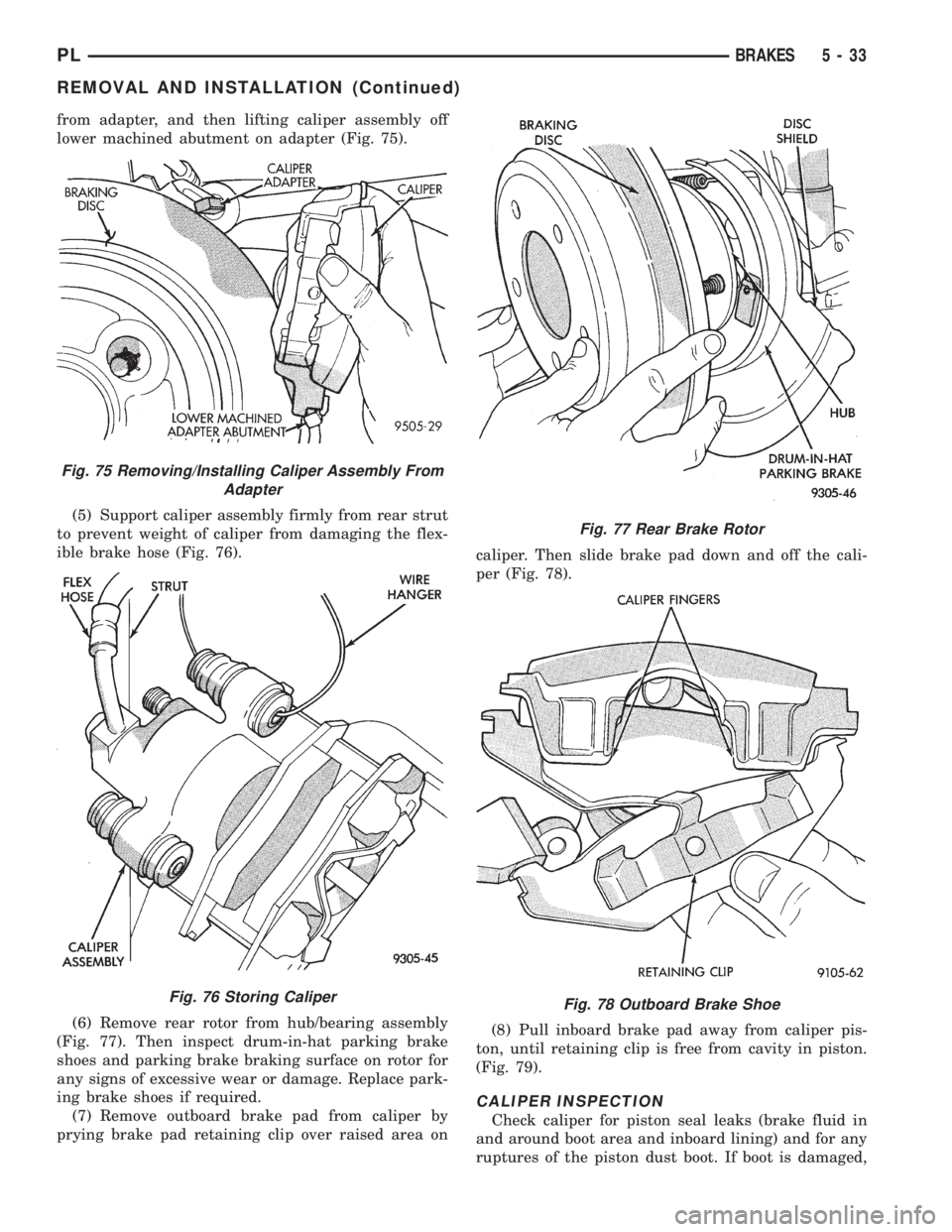
from adapter, and then lifting caliper assembly off
lower machined abutment on adapter (Fig. 75).
(5) Support caliper assembly firmly from rear strut
to prevent weight of caliper from damaging the flex-
ible brake hose (Fig. 76).
(6) Remove rear rotor from hub/bearing assembly
(Fig. 77). Then inspect drum-in-hat parking brake
shoes and parking brake braking surface on rotor for
any signs of excessive wear or damage. Replace park-
ing brake shoes if required.
(7) Remove outboard brake pad from caliper by
prying brake pad retaining clip over raised area oncaliper. Then slide brake pad down and off the cali-
per (Fig. 78).
(8) Pull inboard brake pad away from caliper pis-
ton, until retaining clip is free from cavity in piston.
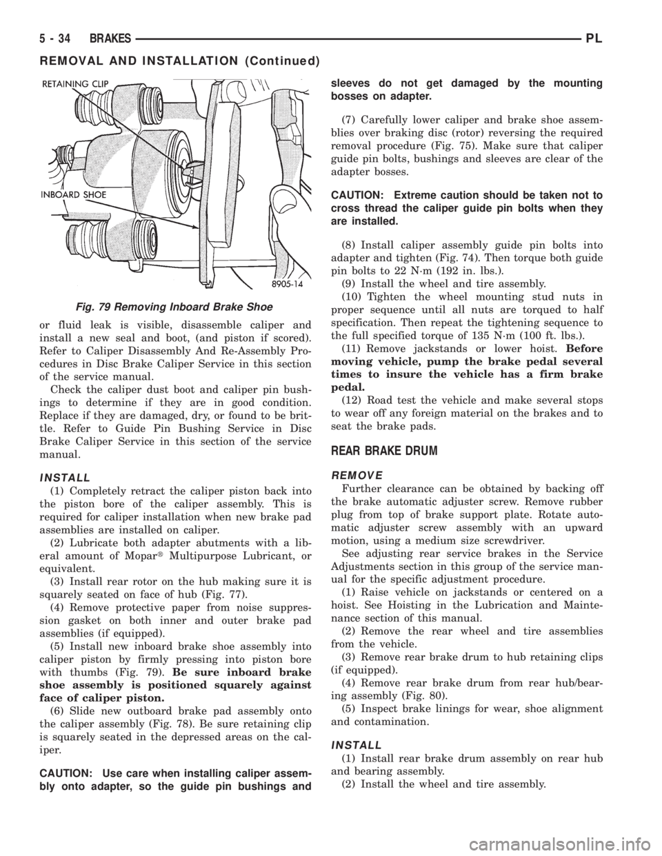
(Fig. 79).
CALIPER INSPECTION
Check caliper for piston seal leaks (brake fluid in
and around boot area and inboard lining) and for any
ruptures of the piston dust boot. If boot is damaged,
Fig. 75 Removing/Installing Caliper Assembly From
Adapter
Fig. 76 Storing Caliper
Fig. 77 Rear Brake Rotor
Fig. 78 Outboard Brake Shoe
PLBRAKES 5 - 33
REMOVAL AND INSTALLATION (Continued)
Page 115 of 1200
or fluid leak is visible, disassemble caliper and
install a new seal and boot, (and piston if scored).
Refer to Caliper Disassembly And Re-Assembly Pro-
cedures in Disc Brake Caliper Service in this section
of the service manual.
Check the caliper dust boot and caliper pin bush-
ings to determine if they are in good condition.
Replace if they are damaged, dry, or found to be brit-
tle. Refer to Guide Pin Bushing Service in Disc
Brake Caliper Service in this section of the service
manual.
INSTALL
(1) Completely retract the caliper piston back into
the piston bore of the caliper assembly. This is
required for caliper installation when new brake pad
assemblies are installed on caliper.
(2) Lubricate both adapter abutments with a lib-
eral amount of MopartMultipurpose Lubricant, or
equivalent.
(3) Install rear rotor on the hub making sure it is
squarely seated on face of hub (Fig. 77).
(4) Remove protective paper from noise suppres-
sion gasket on both inner and outer brake pad
assemblies (if equipped).
(5) Install new inboard brake shoe assembly into
caliper piston by firmly pressing into piston bore
with thumbs (Fig. 79).Be sure inboard brake
shoe assembly is positioned squarely against
face of caliper piston.
(6) Slide new outboard brake pad assembly onto
the caliper assembly (Fig. 78). Be sure retaining clip
is squarely seated in the depressed areas on the cal-
iper.
CAUTION: Use care when installing caliper assem-
bly onto adapter, so the guide pin bushings andsleeves do not get damaged by the mounting
bosses on adapter.
(7) Carefully lower caliper and brake shoe assem-
blies over braking disc (rotor) reversing the required
removal procedure (Fig. 75). Make sure that caliper
guide pin bolts, bushings and sleeves are clear of the
adapter bosses.
CAUTION: Extreme caution should be taken not to
cross thread the caliper guide pin bolts when they
are installed.
(8) Install caliper assembly guide pin bolts into
adapter and tighten (Fig. 74). Then torque both guide
pin bolts to 22 N´m (192 in. lbs.).
(9) Install the wheel and tire assembly.
(10) Tighten the wheel mounting stud nuts in
proper sequence until all nuts are torqued to half
specification. Then repeat the tightening sequence to
the full specified torque of 135 N´m (100 ft. lbs.).
(11) Remove jackstands or lower hoist.Before
moving vehicle, pump the brake pedal several
times to insure the vehicle has a firm brake
pedal.
(12) Road test the vehicle and make several stops
to wear off any foreign material on the brakes and to
seat the brake pads.
REAR BRAKE DRUM
REMOVE
Further clearance can be obtained by backing off
the brake automatic adjuster screw. Remove rubber
plug from top of brake support plate. Rotate auto-
matic adjuster screw assembly with an upward
motion, using a medium size screwdriver.
See adjusting rear service brakes in the Service
Adjustments section in this group of the service man-
ual for the specific adjustment procedure.
(1) Raise vehicle on jackstands or centered on a
hoist. See Hoisting in the Lubrication and Mainte-
nance section of this manual.
(2) Remove the rear wheel and tire assemblies
from the vehicle.
(3) Remove rear brake drum to hub retaining clips
(if equipped).
(4) Remove rear brake drum from rear hub/bear-
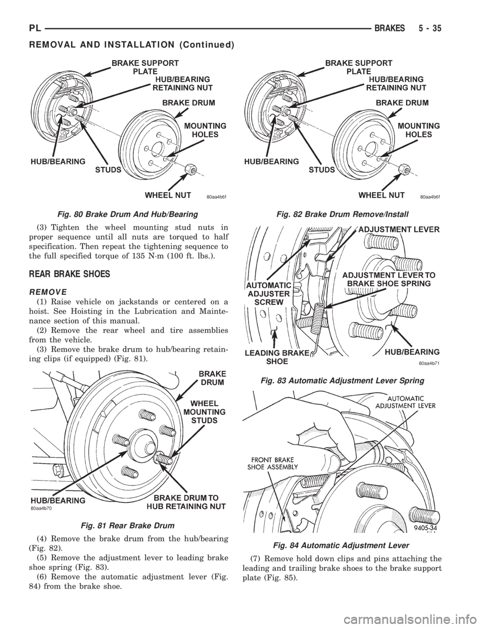
ing assembly (Fig. 80).
(5) Inspect brake linings for wear, shoe alignment
and contamination.
INSTALL
(1) Install rear brake drum assembly on rear hub
and bearing assembly.
(2) Install the wheel and tire assembly.
Fig. 79 Removing Inboard Brake Shoe
5 - 34 BRAKESPL
REMOVAL AND INSTALLATION (Continued)
Page 116 of 1200
(3) Tighten the wheel mounting stud nuts in
proper sequence until all nuts are torqued to half
specification. Then repeat the tightening sequence to
the full specified torque of 135 N´m (100 ft. lbs.).
REAR BRAKE SHOES
REMOVE
(1) Raise vehicle on jackstands or centered on a
hoist. See Hoisting in the Lubrication and Mainte-
nance section of this manual.
(2) Remove the rear wheel and tire assemblies
from the vehicle.
(3) Remove the brake drum to hub/bearing retain-
ing clips (if equipped) (Fig. 81).
(4) Remove the brake drum from the hub/bearing
(Fig. 82).
(5) Remove the adjustment lever to leading brake
shoe spring (Fig. 83).
(6) Remove the automatic adjustment lever (Fig.
84) from the brake shoe.(7) Remove hold down clips and pins attaching the
leading and trailing brake shoes to the brake support
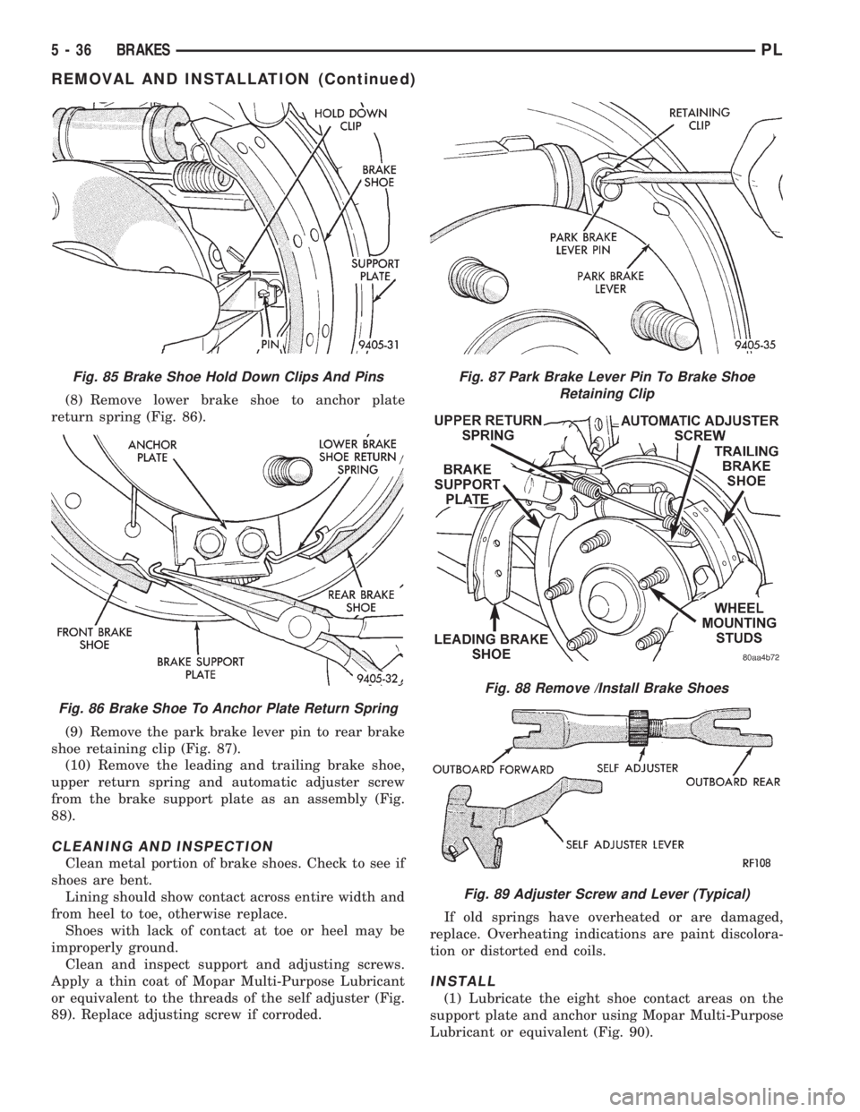
plate (Fig. 85).
Fig. 80 Brake Drum And Hub/Bearing
Fig. 81 Rear Brake Drum
Fig. 82 Brake Drum Remove/Install
Fig. 83 Automatic Adjustment Lever Spring
Fig. 84 Automatic Adjustment Lever
PLBRAKES 5 - 35
REMOVAL AND INSTALLATION (Continued)
Page 117 of 1200
(8) Remove lower brake shoe to anchor plate
return spring (Fig. 86).
(9) Remove the park brake lever pin to rear brake
shoe retaining clip (Fig. 87).
(10) Remove the leading and trailing brake shoe,
upper return spring and automatic adjuster screw
from the brake support plate as an assembly (Fig.
88).
CLEANING AND INSPECTION
Clean metal portion of brake shoes. Check to see if
shoes are bent.
Lining should show contact across entire width and
from heel to toe, otherwise replace.
Shoes with lack of contact at toe or heel may be
improperly ground.
Clean and inspect support and adjusting screws.
Apply a thin coat of Mopar Multi-Purpose Lubricant
or equivalent to the threads of the self adjuster (Fig.
89). Replace adjusting screw if corroded.If old springs have overheated or are damaged,
replace. Overheating indications are paint discolora-
tion or distorted end coils.
INSTALL
(1) Lubricate the eight shoe contact areas on the
support plate and anchor using Mopar Multi-Purpose
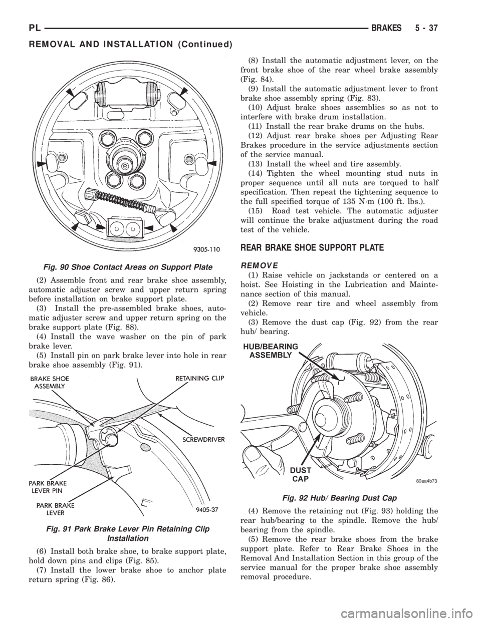
Lubricant or equivalent (Fig. 90).
Fig. 85 Brake Shoe Hold Down Clips And Pins
Fig. 86 Brake Shoe To Anchor Plate Return Spring
Fig. 87 Park Brake Lever Pin To Brake Shoe
Retaining Clip
Fig. 88 Remove /Install Brake Shoes
Fig. 89 Adjuster Screw and Lever (Typical)
5 - 36 BRAKESPL
REMOVAL AND INSTALLATION (Continued)
Page 118 of 1200
(2) Assemble front and rear brake shoe assembly,
automatic adjuster screw and upper return spring
before installation on brake support plate.
(3) Install the pre-assembled brake shoes, auto-
matic adjuster screw and upper return spring on the
brake support plate (Fig. 88).
(4) Install the wave washer on the pin of park
brake lever.
(5) Install pin on park brake lever into hole in rear
brake shoe assembly (Fig. 91).
(6) Install both brake shoe, to brake support plate,
hold down pins and clips (Fig. 85).
(7) Install the lower brake shoe to anchor plate
return spring (Fig. 86).(8) Install the automatic adjustment lever, on the
front brake shoe of the rear wheel brake assembly
(Fig. 84).
(9) Install the automatic adjustment lever to front
brake shoe assembly spring (Fig. 83).
(10) Adjust brake shoes assemblies so as not to
interfere with brake drum installation.
(11) Install the rear brake drums on the hubs.
(12) Adjust rear brake shoes per Adjusting Rear
Brakes procedure in the service adjustments section
of the service manual.
(13) Install the wheel and tire assembly.
(14) Tighten the wheel mounting stud nuts in
proper sequence until all nuts are torqued to half
specification. Then repeat the tightening sequence to
the full specified torque of 135 N´m (100 ft. lbs.).
(15) Road test vehicle. The automatic adjuster
will continue the brake adjustment during the road
test of the vehicle.
REAR BRAKE SHOE SUPPORT PLATE
REMOVE
(1) Raise vehicle on jackstands or centered on a
hoist. See Hoisting in the Lubrication and Mainte-
nance section of this manual.
(2) Remove rear tire and wheel assembly from
vehicle.
(3) Remove the dust cap (Fig. 92) from the rear
hub/ bearing.
(4) Remove the retaining nut (Fig. 93) holding the
rear hub/bearing to the spindle. Remove the hub/
bearing from the spindle.
(5) Remove the rear brake shoes from the brake
support plate. Refer to Rear Brake Shoes in the
Removal And Installation Section in this group of the
service manual for the proper brake shoe assembly
removal procedure.
Fig. 90 Shoe Contact Areas on Support Plate
Fig. 91 Park Brake Lever Pin Retaining Clip
Installation
Fig. 92 Hub/ Bearing Dust Cap
PLBRAKES 5 - 37
REMOVAL AND INSTALLATION (Continued)
Page 119 of 1200
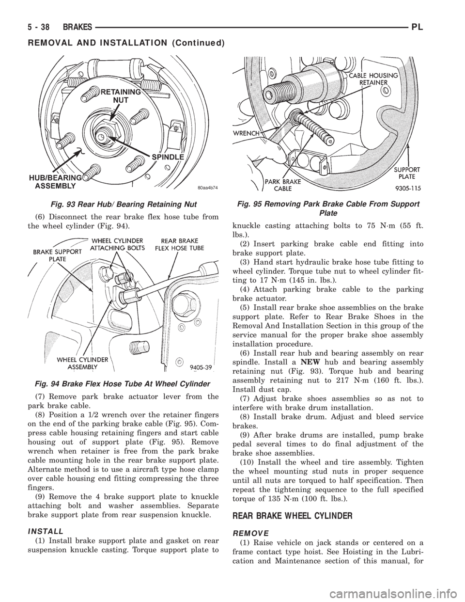
(6) Disconnect the rear brake flex hose tube from
the wheel cylinder (Fig. 94).
(7) Remove park brake actuator lever from the
park brake cable.
(8) Position a 1/2 wrench over the retainer fingers
on the end of the parking brake cable (Fig. 95). Com-
press cable housing retaining fingers and start cable
housing out of support plate (Fig. 95). Remove
wrench when retainer is free from the park brake
cable mounting hole in the rear brake support plate.
Alternate method is to use a aircraft type hose clamp
over cable housing end fitting compressing the three
fingers.
(9) Remove the 4 brake support plate to knuckle
attaching bolt and washer assemblies. Separate
brake support plate from rear suspension knuckle.
INSTALL
(1) Install brake support plate and gasket on rear
suspension knuckle casting. Torque support plate toknuckle casting attaching bolts to 75 N´m (55 ft.
lbs.).
(2) Insert parking brake cable end fitting into
brake support plate.
(3) Hand start hydraulic brake hose tube fitting to
wheel cylinder. Torque tube nut to wheel cylinder fit-
ting to 17 N´m (145 in. lbs.).
(4) Attach parking brake cable to the parking
brake actuator.
(5) Install rear brake shoe assemblies on the brake
support plate. Refer to Rear Brake Shoes in the
Removal And Installation Section in this group of the
service manual for the proper brake shoe assembly
installation procedure.
(6) Install rear hub and bearing assembly on rear
spindle. Install aNEWhub and bearing assembly
retaining nut (Fig. 93). Torque hub and bearing
assembly retaining nut to 217 N´m (160 ft. lbs.).
Install dust cap.
(7) Adjust brake shoes assemblies so as not to
interfere with brake drum installation.
(8) Install brake drum. Adjust and bleed service
brakes.
(9) After brake drums are installed, pump brake
pedal several times to do final adjustment of the
brake shoe assemblies.
(10) Install the wheel and tire assembly. Tighten
the wheel mounting stud nuts in proper sequence
until all nuts are torqued to half specification. Then
repeat the tightening sequence to the full specified
torque of 135 N´m (100 ft. lbs.).
REAR BRAKE WHEEL CYLINDER
REMOVE
(1) Raise vehicle on jack stands or centered on a
frame contact type hoist. See Hoisting in the Lubri-
cation and Maintenance section of this manual, for
Fig. 93 Rear Hub/ Bearing Retaining Nut
Fig. 94 Brake Flex Hose Tube At Wheel Cylinder
Fig. 95 Removing Park Brake Cable From Support
Plate
5 - 38 BRAKESPL
REMOVAL AND INSTALLATION (Continued)
Page 120 of 1200
the required lifting procedure to be used for this
vehicle.
(2) Remove the tire and wheel assembly from the
vehicle.
(3) Remove rear brake drum.
(4) Remove rear brake shoe assemblies from the
brake support plate. Refer to Rear Brake Shoes in
the Removal And Installation Section in this group of
the service manual for the proper brake shoe assem-
bly removal procedure.
(5) If brake shoes are wet with grease or brake
fluid, remove and replace.
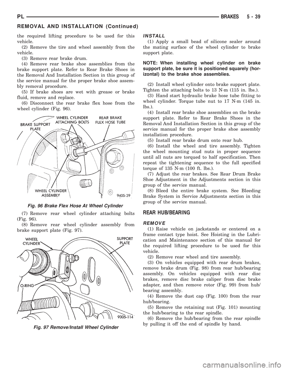
(6) Disconnect the rear brake flex hose from the
wheel cylinder (Fig. 96).
(7) Remove rear wheel cylinder attaching bolts
(Fig. 96).
(8) Remove rear wheel cylinder assembly from
brake support plate (Fig. 97).INSTALL
(1) Apply a small bead of silicone sealer around
the mating surface of the wheel cylinder to brake
support plate.
NOTE: When installing wheel cylinder on brake
support plate, be sure it is positioned squarely (hor-
izontal) to the brake shoe assemblies.
(2) Install wheel cylinder onto brake support plate.
Tighten the attaching bolts to 13 N´m (115 in. lbs.).
(3) Hand start hydraulic brake hose tube fitting to
wheel cylinder. Torque tube nut to 17 N´m (145 in.
lbs.).
(4) Install rear brake shoe assemblies on the brake
support plate. Refer to Rear Brake Shoes in the
Removal And Installation Section in this group of the
service manual for the proper brake shoe assembly
installation procedure.
(5) Install rear brake drum onto rear hub.
(6) Install the wheel and tire assembly. Tighten
the wheel mounting stud nuts in proper sequence
until all nuts are torqued to half specification. Then
repeat the tightening sequence to the full specified
torque of 135 N´m (100 ft. lbs.).
(7) Adjust the rear brakes. See Rear Drum Brake
Shoe Adjustment in the Adjustments section in this
group of the service manual.
(8) Bleed the entire brake system. See Bleeding
Brake System in Service Adjustments section in this
group of the service manual.
REAR HUB/BEARING
REMOVE
(1) Raise vehicle on jackstands or centered on a
frame contact type hoist. See Hoisting in the Lubri-
cation and Maintenance section of this manual for
the required lifting procedure to be used for this
vehicle.
(2) Remove rear wheel and tire assembly.
(3) On vehicles equipped with rear drum brakes,
remove brake drum (Fig. 98) from rear hub/bearing
assembly. On vehicles equipped with rear disc
brakes, remove disc brake caliper from disc brake
adapter, and then remove rotor (Fig. 99) from hub/
bearing assembly.
(4) Remove the dust cap (Fig. 100) from the rear
hub/bearing.
(5) Remove the retaining nut (Fig. 101) mounting
the hub/bearing to the rear spindle.
(6) Remove the hub/bearing from the rear spindle
by pulling it off the end of spindle by hand.
Fig. 96 Brake Flex Hose At Wheel Cylinder
Fig. 97 Remove/Install Wheel Cylinder
PLBRAKES 5 - 39
REMOVAL AND INSTALLATION (Continued)