DODGE NEON 1999 Service Repair Manual
Manufacturer: DODGE, Model Year: 1999, Model line: NEON, Model: DODGE NEON 1999Pages: 1200, PDF Size: 35.29 MB
Page 241 of 1200
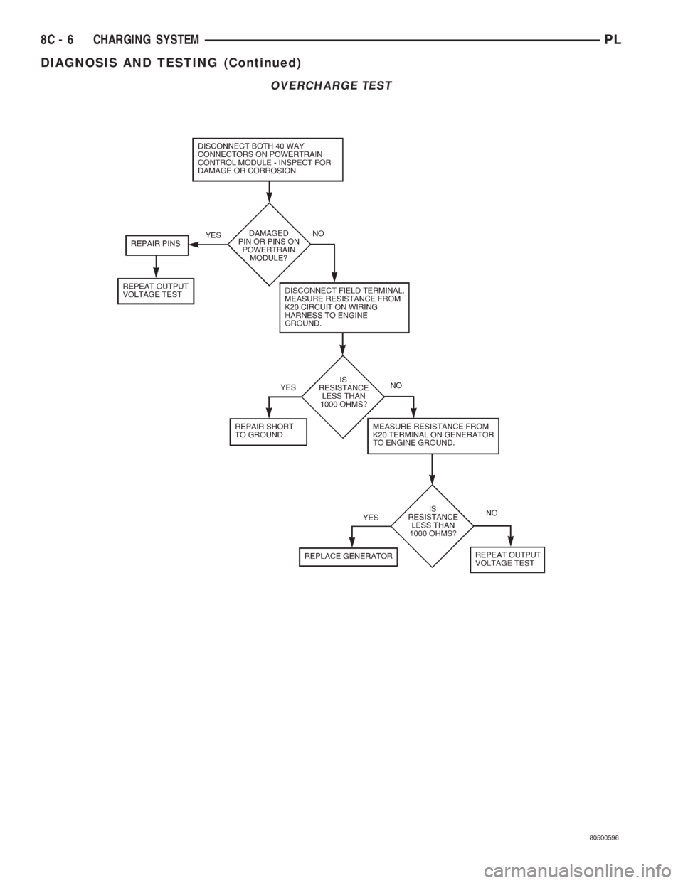
OVERCHARGE TEST
8C - 6 CHARGING SYSTEMPL
DIAGNOSIS AND TESTING (Continued)
Page 242 of 1200
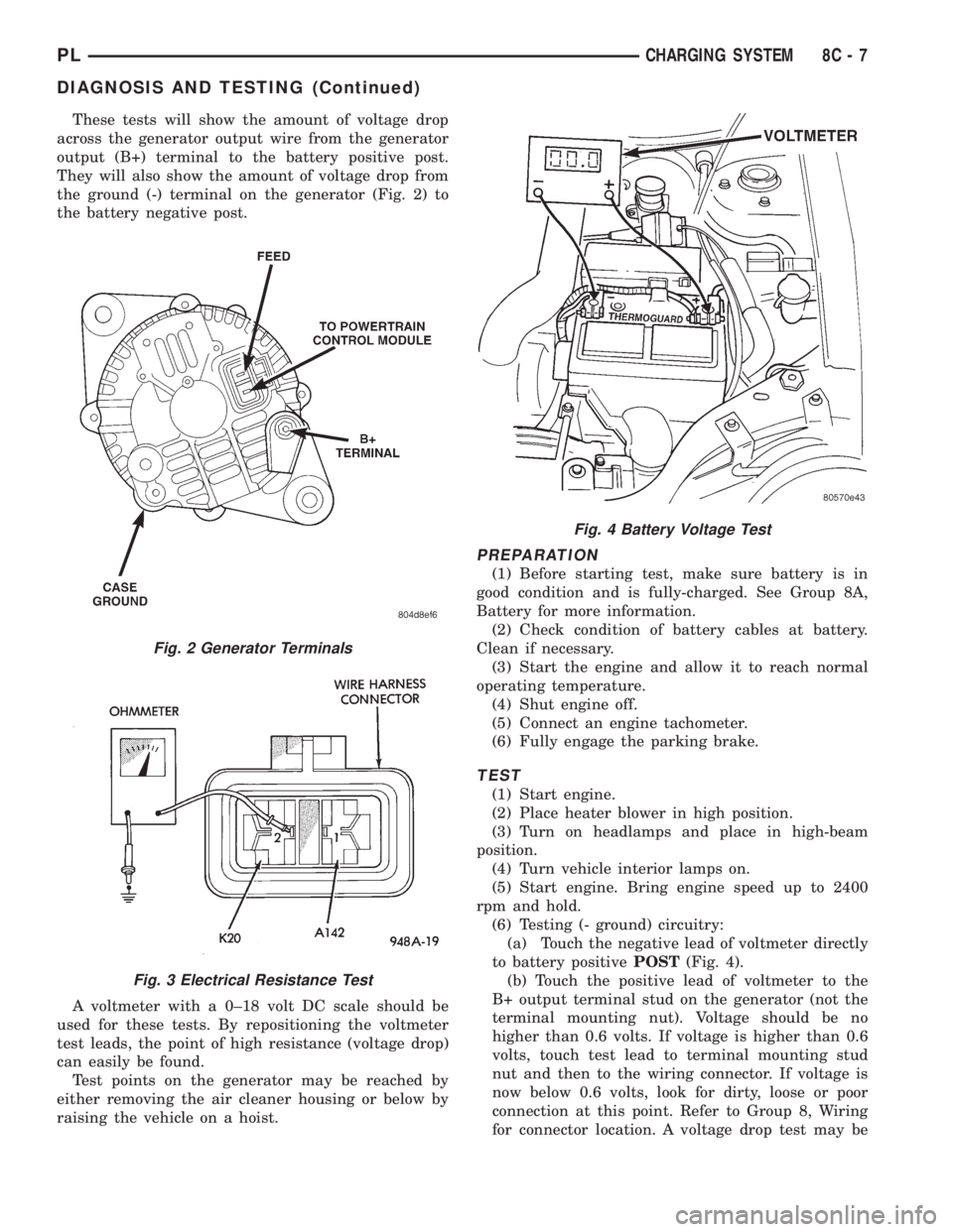
These tests will show the amount of voltage drop
across the generator output wire from the generator
output (B+) terminal to the battery positive post.
They will also show the amount of voltage drop from
the ground (-) terminal on the generator (Fig. 2) to
the battery negative post.
A voltmeter with a 0±18 volt DC scale should be
used for these tests. By repositioning the voltmeter
test leads, the point of high resistance (voltage drop)
can easily be found.
Test points on the generator may be reached by
either removing the air cleaner housing or below by
raising the vehicle on a hoist.
PREPARATION
(1) Before starting test, make sure battery is in
good condition and is fully-charged. See Group 8A,
Battery for more information.
(2) Check condition of battery cables at battery.
Clean if necessary.
(3) Start the engine and allow it to reach normal
operating temperature.
(4) Shut engine off.
(5) Connect an engine tachometer.
(6) Fully engage the parking brake.
TEST
(1) Start engine.
(2) Place heater blower in high position.
(3) Turn on headlamps and place in high-beam
position.
(4) Turn vehicle interior lamps on.
(5) Start engine. Bring engine speed up to 2400
rpm and hold.
(6) Testing (- ground) circuitry:
(a) Touch the negative lead of voltmeter directly
to battery positivePOST(Fig. 4).
(b) Touch the positive lead of voltmeter to the
B+ output terminal stud on the generator (not the
terminal mounting nut). Voltage should be no
higher than 0.6 volts. If voltage is higher than 0.6
volts, touch test lead to terminal mounting stud
nut and then to the wiring connector. If voltage is
now below 0.6 volts, look for dirty, loose or poor
connection at this point. Refer to Group 8, Wiring
for connector location. A voltage drop test may be
Fig. 2 Generator Terminals
Fig. 3 Electrical Resistance Test
Fig. 4 Battery Voltage Test
PLCHARGING SYSTEM 8C - 7
DIAGNOSIS AND TESTING (Continued)
Page 243 of 1200
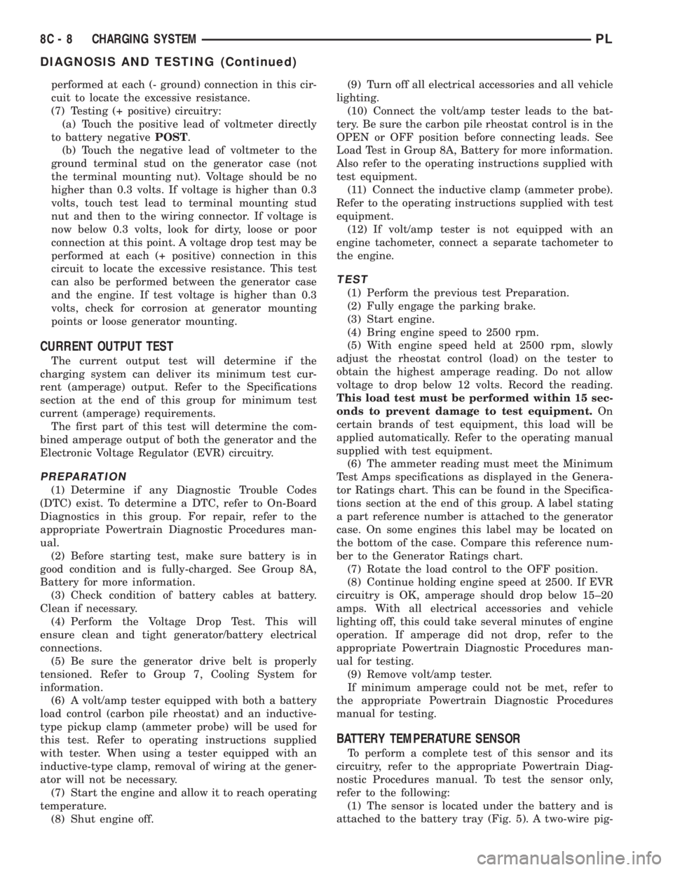
performed at each (- ground) connection in this cir-
cuit to locate the excessive resistance.
(7) Testing (+ positive) circuitry:
(a) Touch the positive lead of voltmeter directly
to battery negativePOST.
(b) Touch the negative lead of voltmeter to the
ground terminal stud on the generator case (not
the terminal mounting nut). Voltage should be no
higher than 0.3 volts. If voltage is higher than 0.3
volts, touch test lead to terminal mounting stud
nut and then to the wiring connector. If voltage is
now below 0.3 volts, look for dirty, loose or poor
connection at this point. A voltage drop test may be
performed at each (+ positive) connection in this
circuit to locate the excessive resistance. This test
can also be performed between the generator case
and the engine. If test voltage is higher than 0.3
volts, check for corrosion at generator mounting
points or loose generator mounting.
CURRENT OUTPUT TEST
The current output test will determine if the
charging system can deliver its minimum test cur-
rent (amperage) output. Refer to the Specifications
section at the end of this group for minimum test
current (amperage) requirements.
The first part of this test will determine the com-
bined amperage output of both the generator and the
Electronic Voltage Regulator (EVR) circuitry.
PREPARATION
(1) Determine if any Diagnostic Trouble Codes
(DTC) exist. To determine a DTC, refer to On-Board
Diagnostics in this group. For repair, refer to the
appropriate Powertrain Diagnostic Procedures man-
ual.
(2) Before starting test, make sure battery is in
good condition and is fully-charged. See Group 8A,
Battery for more information.
(3) Check condition of battery cables at battery.
Clean if necessary.
(4) Perform the Voltage Drop Test. This will
ensure clean and tight generator/battery electrical
connections.
(5) Be sure the generator drive belt is properly
tensioned. Refer to Group 7, Cooling System for
information.
(6) A volt/amp tester equipped with both a battery
load control (carbon pile rheostat) and an inductive-
type pickup clamp (ammeter probe) will be used for
this test. Refer to operating instructions supplied
with tester. When using a tester equipped with an
inductive-type clamp, removal of wiring at the gener-
ator will not be necessary.
(7) Start the engine and allow it to reach operating
temperature.
(8) Shut engine off.(9) Turn off all electrical accessories and all vehicle
lighting.
(10) Connect the volt/amp tester leads to the bat-
tery. Be sure the carbon pile rheostat control is in the
OPEN or OFF position before connecting leads. See
Load Test in Group 8A, Battery for more information.
Also refer to the operating instructions supplied with
test equipment.
(11) Connect the inductive clamp (ammeter probe).
Refer to the operating instructions supplied with test
equipment.
(12) If volt/amp tester is not equipped with an
engine tachometer, connect a separate tachometer to
the engine.
TEST
(1) Perform the previous test Preparation.
(2) Fully engage the parking brake.
(3) Start engine.
(4) Bring engine speed to 2500 rpm.
(5) With engine speed held at 2500 rpm, slowly
adjust the rheostat control (load) on the tester to
obtain the highest amperage reading. Do not allow
voltage to drop below 12 volts. Record the reading.
This load test must be performed within 15 sec-
onds to prevent damage to test equipment.On
certain brands of test equipment, this load will be
applied automatically. Refer to the operating manual
supplied with test equipment.
(6) The ammeter reading must meet the Minimum
Test Amps specifications as displayed in the Genera-
tor Ratings chart. This can be found in the Specifica-
tions section at the end of this group. A label stating
a part reference number is attached to the generator
case. On some engines this label may be located on
the bottom of the case. Compare this reference num-
ber to the Generator Ratings chart.
(7) Rotate the load control to the OFF position.
(8) Continue holding engine speed at 2500. If EVR
circuitry is OK, amperage should drop below 15±20
amps. With all electrical accessories and vehicle
lighting off, this could take several minutes of engine
operation. If amperage did not drop, refer to the
appropriate Powertrain Diagnostic Procedures man-
ual for testing.
(9) Remove volt/amp tester.
If minimum amperage could not be met, refer to
the appropriate Powertrain Diagnostic Procedures
manual for testing.
BATTERY TEMPERATURE SENSOR
To perform a complete test of this sensor and its
circuitry, refer to the appropriate Powertrain Diag-
nostic Procedures manual. To test the sensor only,
refer to the following:
(1) The sensor is located under the battery and is
attached to the battery tray (Fig. 5). A two-wire pig-
8C - 8 CHARGING SYSTEMPL
DIAGNOSIS AND TESTING (Continued)
Page 244 of 1200
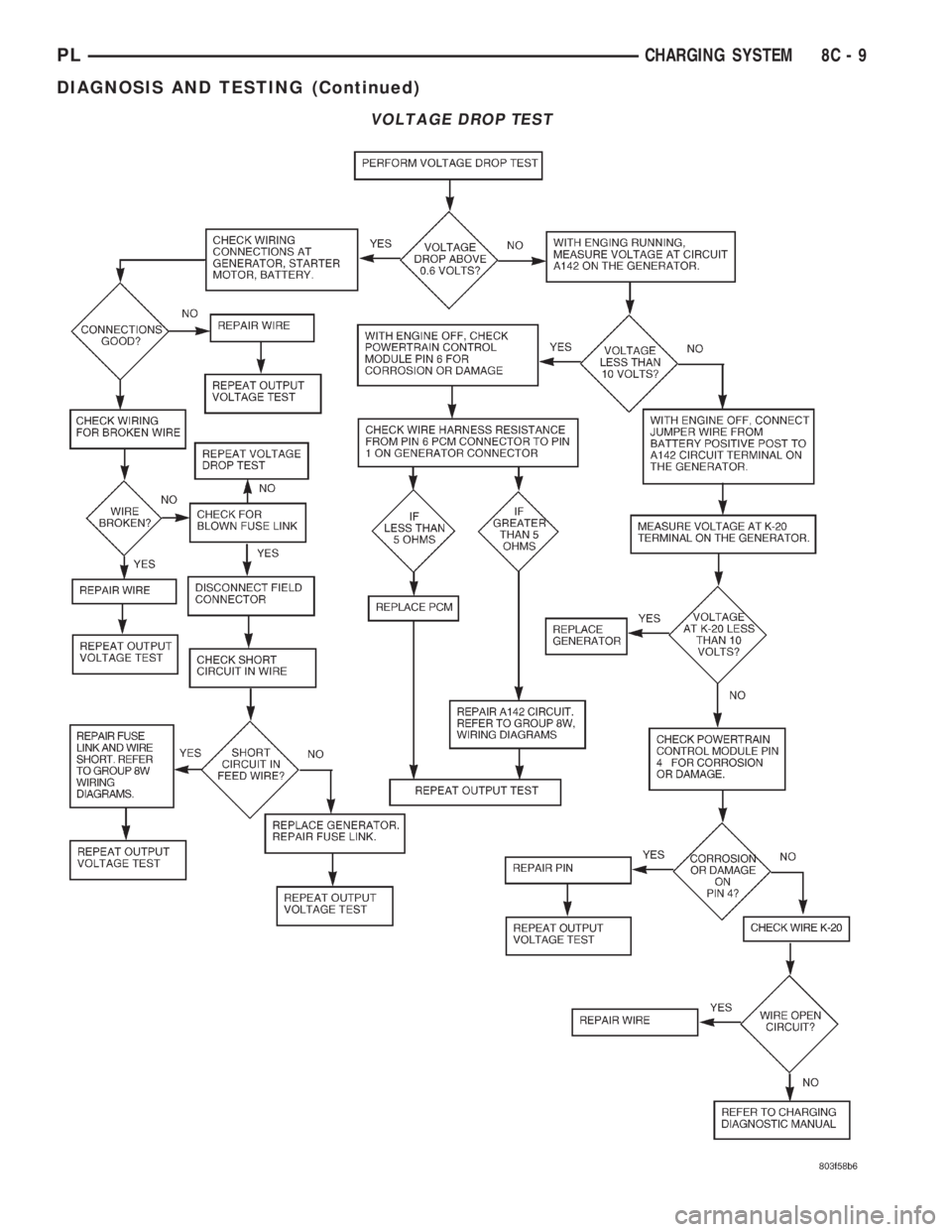
VOLTAGE DROP TEST
PLCHARGING SYSTEM 8C - 9
DIAGNOSIS AND TESTING (Continued)
Page 245 of 1200
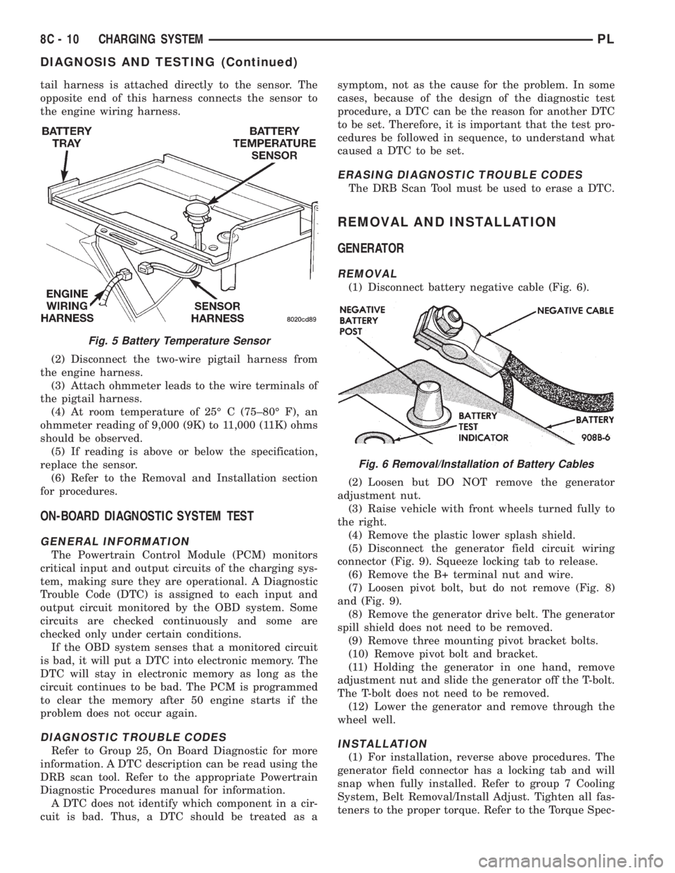
tail harness is attached directly to the sensor. The
opposite end of this harness connects the sensor to
the engine wiring harness.
(2) Disconnect the two-wire pigtail harness from
the engine harness.
(3) Attach ohmmeter leads to the wire terminals of
the pigtail harness.
(4) At room temperature of 25É C (75±80É F), an
ohmmeter reading of 9,000 (9K) to 11,000 (11K) ohms
should be observed.
(5) If reading is above or below the specification,
replace the sensor.
(6) Refer to the Removal and Installation section
for procedures.
ON-BOARD DIAGNOSTIC SYSTEM TEST
GENERAL INFORMATION
The Powertrain Control Module (PCM) monitors
critical input and output circuits of the charging sys-
tem, making sure they are operational. A Diagnostic
Trouble Code (DTC) is assigned to each input and
output circuit monitored by the OBD system. Some
circuits are checked continuously and some are
checked only under certain conditions.
If the OBD system senses that a monitored circuit
is bad, it will put a DTC into electronic memory. The
DTC will stay in electronic memory as long as the
circuit continues to be bad. The PCM is programmed
to clear the memory after 50 engine starts if the
problem does not occur again.
DIAGNOSTIC TROUBLE CODES
Refer to Group 25, On Board Diagnostic for more
information. A DTC description can be read using the
DRB scan tool. Refer to the appropriate Powertrain
Diagnostic Procedures manual for information.
A DTC does not identify which component in a cir-
cuit is bad. Thus, a DTC should be treated as asymptom, not as the cause for the problem. In some
cases, because of the design of the diagnostic test
procedure, a DTC can be the reason for another DTC
to be set. Therefore, it is important that the test pro-
cedures be followed in sequence, to understand what
caused a DTC to be set.
ERASING DIAGNOSTIC TROUBLE CODES
The DRB Scan Tool must be used to erase a DTC.
REMOVAL AND INSTALLATION
GENERATOR
REMOVAL
(1) Disconnect battery negative cable (Fig. 6).
(2) Loosen but DO NOT remove the generator
adjustment nut.
(3) Raise vehicle with front wheels turned fully to
the right.
(4) Remove the plastic lower splash shield.
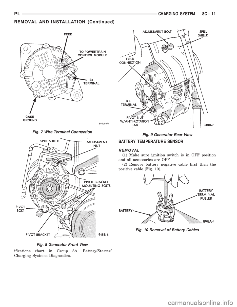
(5) Disconnect the generator field circuit wiring
connector (Fig. 9). Squeeze locking tab to release.
(6) Remove the B+ terminal nut and wire.
(7) Loosen pivot bolt, but do not remove (Fig. 8)
and (Fig. 9).
(8) Remove the generator drive belt. The generator
spill shield does not need to be removed.
(9) Remove three mounting pivot bracket bolts.
(10) Remove pivot bolt and bracket.
(11) Holding the generator in one hand, remove
adjustment nut and slide the generator off the T-bolt.
The T-bolt does not need to be removed.
(12) Lower the generator and remove through the
wheel well.
INSTALLATION
(1) For installation, reverse above procedures. The
generator field connector has a locking tab and will
snap when fully installed. Refer to group 7 Cooling
System, Belt Removal/Install Adjust. Tighten all fas-
teners to the proper torque. Refer to the Torque Spec-
Fig. 5 Battery Temperature Sensor
Fig. 6 Removal/Installation of Battery Cables
8C - 10 CHARGING SYSTEMPL
DIAGNOSIS AND TESTING (Continued)
Page 246 of 1200
ifications chart in Group 8A, Battery/Starter/
Charging Systems Diagnostics.
BATTERY TEMPERATURE SENSOR
REMOVAL
(1) Make sure ignition switch is in OFF position
and all accessories are OFF.
(2) Remove battery negative cable first then the
positive cable (Fig. 10).
Fig. 7 Wire Terminal Connection
Fig. 8 Generator Front View
Fig. 9 Generator Rear View
Fig. 10 Removal of Battery Cables
PLCHARGING SYSTEM 8C - 11
REMOVAL AND INSTALLATION (Continued)
Page 247 of 1200
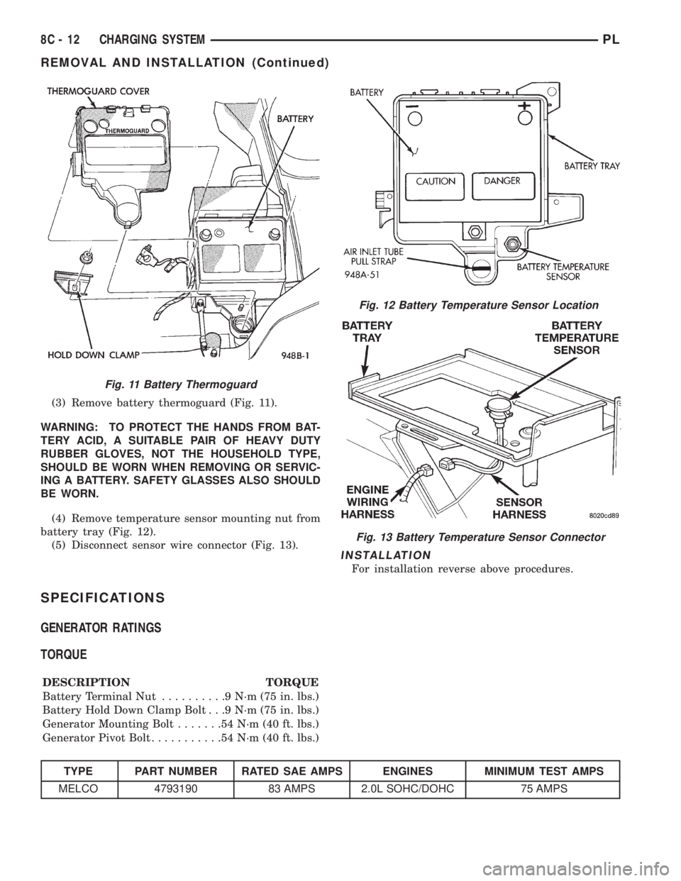
(3) Remove battery thermoguard (Fig. 11).
WARNING: TO PROTECT THE HANDS FROM BAT-
TERY ACID, A SUITABLE PAIR OF HEAVY DUTY
RUBBER GLOVES, NOT THE HOUSEHOLD TYPE,
SHOULD BE WORN WHEN REMOVING OR SERVIC-
ING A BATTERY. SAFETY GLASSES ALSO SHOULD
BE WORN.
(4) Remove temperature sensor mounting nut from
battery tray (Fig. 12).
(5) Disconnect sensor wire connector (Fig. 13).
INSTALLATION
For installation reverse above procedures.
SPECIFICATIONS
GENERATOR RATINGS
TORQUE
DESCRIPTION TORQUE
Battery Terminal Nut..........9N´m(75in.lbs.)
Battery Hold Down Clamp Bolt . . .9 N´m (75 in. lbs.)
Generator Mounting Bolt.......54N´m(40ft.lbs.)
Generator Pivot Bolt...........54N´m(40ft.lbs.)
TYPE PART NUMBER RATED SAE AMPS ENGINES MINIMUM TEST AMPS
MELCO 4793190 83 AMPS 2.0L SOHC/DOHC 75 AMPS
Fig. 11 Battery Thermoguard
Fig. 12 Battery Temperature Sensor Location
Fig. 13 Battery Temperature Sensor Connector
8C - 12 CHARGING SYSTEMPL
REMOVAL AND INSTALLATION (Continued)
Page 248 of 1200

CHARGING SYSTEM
CONTENTS
page
DIAGNOSIS AND TESTING
CHARGING SYSTEM.................... 2
PLCHARGING SYSTEM 8C - 1
Page 249 of 1200
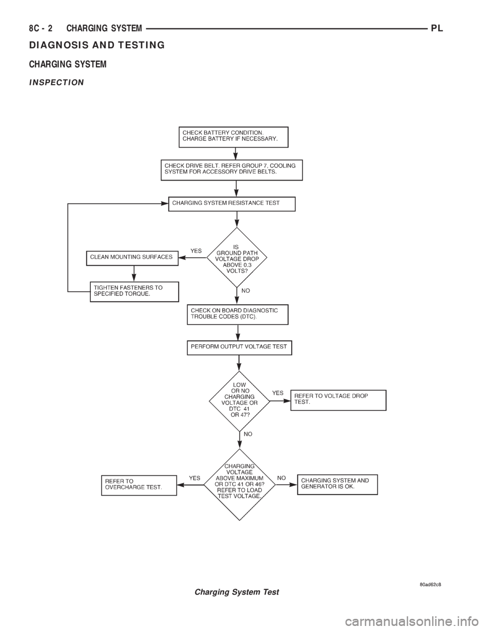
DIAGNOSIS AND TESTING
CHARGING SYSTEM
INSPECTION
Charging System Test
8C - 2 CHARGING SYSTEMPL
Page 250 of 1200
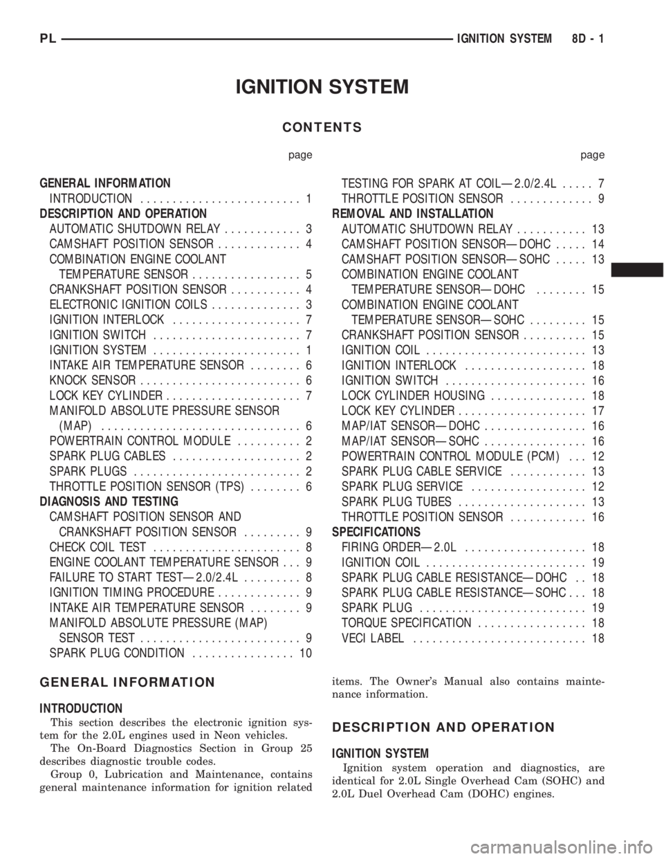
IGNITION SYSTEM
CONTENTS
page page
GENERAL INFORMATION
INTRODUCTION......................... 1
DESCRIPTION AND OPERATION
AUTOMATIC SHUTDOWN RELAY............ 3
CAMSHAFT POSITION SENSOR............. 4
COMBINATION ENGINE COOLANT
TEMPERATURE SENSOR................. 5
CRANKSHAFT POSITION SENSOR........... 4
ELECTRONIC IGNITION COILS.............. 3
IGNITION INTERLOCK.................... 7
IGNITION SWITCH....................... 7
IGNITION SYSTEM....................... 1
INTAKE AIR TEMPERATURE SENSOR........ 6
KNOCK SENSOR......................... 6
LOCK KEY CYLINDER..................... 7
MANIFOLD ABSOLUTE PRESSURE SENSOR
(MAP)............................... 6
POWERTRAIN CONTROL MODULE.......... 2
SPARK PLUG CABLES.................... 2
SPARK PLUGS.......................... 2
THROTTLE POSITION SENSOR (TPS)........ 6
DIAGNOSIS AND TESTING
CAMSHAFT POSITION SENSOR AND
CRANKSHAFT POSITION SENSOR......... 9
CHECK COIL TEST....................... 8
ENGINE COOLANT TEMPERATURE SENSOR . . . 9
FAILURE TO START TESTÐ2.0/2.4L......... 8
IGNITION TIMING PROCEDURE............. 9
INTAKE AIR TEMPERATURE SENSOR........ 9
MANIFOLD ABSOLUTE PRESSURE (MAP)
SENSOR TEST......................... 9
SPARK PLUG CONDITION................ 10TESTING FOR SPARK AT COILÐ2.0/2.4L..... 7
THROTTLE POSITION SENSOR............. 9
REMOVAL AND INSTALLATION
AUTOMATIC SHUTDOWN RELAY........... 13
CAMSHAFT POSITION SENSORÐDOHC..... 14
CAMSHAFT POSITION SENSORÐSOHC..... 13
COMBINATION ENGINE COOLANT
TEMPERATURE SENSORÐDOHC........ 15
COMBINATION ENGINE COOLANT
TEMPERATURE SENSORÐSOHC......... 15
CRANKSHAFT POSITION SENSOR.......... 15
IGNITION COIL......................... 13
IGNITION INTERLOCK................... 18
IGNITION SWITCH...................... 16
LOCK CYLINDER HOUSING............... 18
LOCK KEY CYLINDER.................... 17
MAP/IAT SENSORÐDOHC................ 16
MAP/IAT SENSORÐSOHC................ 16
POWERTRAIN CONTROL MODULE (PCM) . . . 12
SPARK PLUG CABLE SERVICE............ 13
SPARK PLUG SERVICE.................. 12
SPARK PLUG TUBES.................... 13
THROTTLE POSITION SENSOR............ 16
SPECIFICATIONS
FIRING ORDERÐ2.0L................... 18
IGNITION COIL......................... 19
SPARK PLUG CABLE RESISTANCEÐDOHC . . 18
SPARK PLUG CABLE RESISTANCEÐSOHC . . . 18
SPARK PLUG.......................... 19
TORQUE SPECIFICATION................. 18
VECI LABEL........................... 18
GENERAL INFORMATION
INTRODUCTION
This section describes the electronic ignition sys-
tem for the 2.0L engines used in Neon vehicles.
The On-Board Diagnostics Section in Group 25
describes diagnostic trouble codes.
Group 0, Lubrication and Maintenance, contains
general maintenance information for ignition relateditems. The Owner's Manual also contains mainte-
nance information.DESCRIPTION AND OPERATION
IGNITION SYSTEM
Ignition system operation and diagnostics, are
identical for 2.0L Single Overhead Cam (SOHC) and
2.0L Duel Overhead Cam (DOHC) engines.
PLIGNITION SYSTEM 8D - 1