DODGE NEON 1999 Service Repair Manual
Manufacturer: DODGE, Model Year: 1999, Model line: NEON, Model: DODGE NEON 1999Pages: 1200, PDF Size: 35.29 MB
Page 931 of 1200
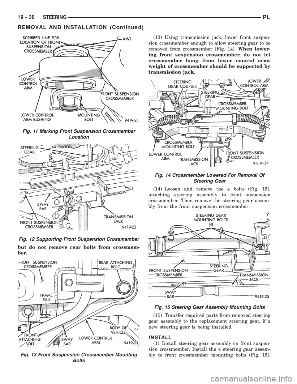
but do not remove rear bolts from crossmem-
ber.(13) Using transmission jack, lower front suspen-
sion crossmember enough to allow steering gear to be
removed from crossmember (Fig. 14).When lower-
ing front suspension crossmember, do not let
crossmember hang from lower control arms
weight of crossmember should be supported by
transmission jack.
(14) Loosen and remove the 4 bolts (Fig. 15),
attaching steering assembly to front suspension
crossmember. Then remove the steering gear assem-
bly from the front suspension crossmember.
(15) Transfer required parts from removed steering
gear assembly to the replacement steering gear, if a
new steering gear is being installed.
INSTALL
(1) Install steering gear assembly on front suspen-
sion crossmember. Install the 4 steering gear assem-
bly to front crossmember mounting bolts (Fig. 15).
Fig. 11 Marking Front Suspension Crossmember
Location
Fig. 12 Supporting Front Suspension Crossmember
Fig. 13 Front Suspension Crossmember Mounting
Bolts
Fig. 14 Crossmember Lowered For Removal Of
Steering Gear
Fig. 15 Steering Gear Assembly Mounting Bolts
19 - 30 STEERINGPL
REMOVAL AND INSTALLATION (Continued)
Page 932 of 1200
Torque the 4 steering gear mounting bolts to 68 N´m
(50 ft. lbs.).
(2) Using the transmission jack, raise front sus-
pension crossmember and steering gear against body
and frame rails of vehicle. Start the 2 rear bolts into
tapping plates, attaching front suspension crossmem-
ber to body of vehicle (Fig. 13). Then install the 2
front bolts, attaching front suspension crossmember
to frame rails of vehicle (Fig. 13). Tighten the 4
mounting bolts, until front suspension crossmember
is against body of vehicle at the 4 mounting points.
Then torque the 4 mounting bolts to 2 N´m (20 in.
lbs.) to hold front suspension crossmember in posi-
tion.
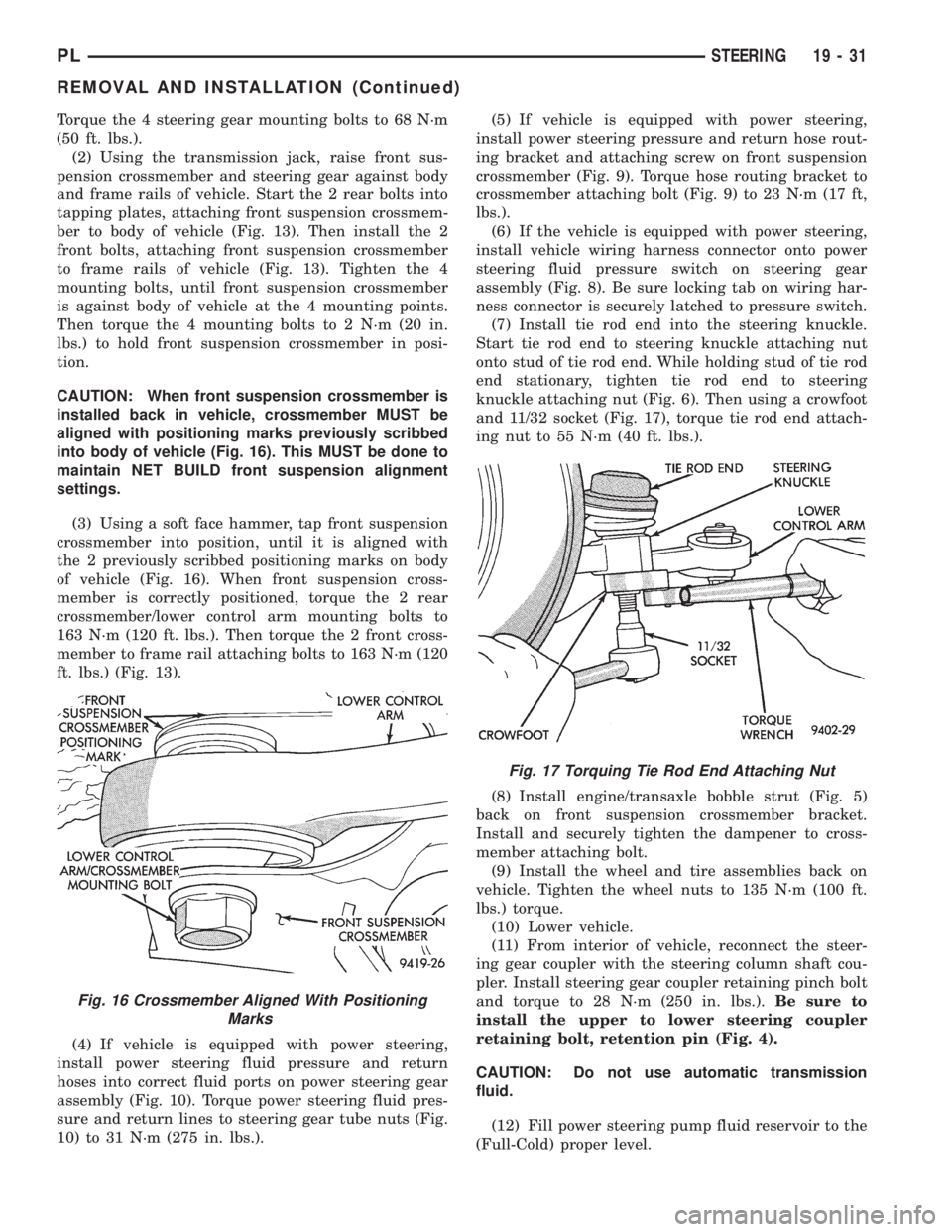
CAUTION: When front suspension crossmember is
installed back in vehicle, crossmember MUST be
aligned with positioning marks previously scribbed
into body of vehicle (Fig. 16). This MUST be done to
maintain NET BUILD front suspension alignment
settings.
(3) Using a soft face hammer, tap front suspension
crossmember into position, until it is aligned with
the 2 previously scribbed positioning marks on body
of vehicle (Fig. 16). When front suspension cross-
member is correctly positioned, torque the 2 rear
crossmember/lower control arm mounting bolts to
163 N´m (120 ft. lbs.). Then torque the 2 front cross-
member to frame rail attaching bolts to 163 N´m (120
ft. lbs.) (Fig. 13).
(4) If vehicle is equipped with power steering,
install power steering fluid pressure and return
hoses into correct fluid ports on power steering gear
assembly (Fig. 10). Torque power steering fluid pres-
sure and return lines to steering gear tube nuts (Fig.
10) to 31 N´m (275 in. lbs.).(5) If vehicle is equipped with power steering,
install power steering pressure and return hose rout-
ing bracket and attaching screw on front suspension
crossmember (Fig. 9). Torque hose routing bracket to
crossmember attaching bolt (Fig. 9) to 23 N´m (17 ft,
lbs.).
(6) If the vehicle is equipped with power steering,
install vehicle wiring harness connector onto power
steering fluid pressure switch on steering gear
assembly (Fig. 8). Be sure locking tab on wiring har-
ness connector is securely latched to pressure switch.
(7) Install tie rod end into the steering knuckle.
Start tie rod end to steering knuckle attaching nut
onto stud of tie rod end. While holding stud of tie rod
end stationary, tighten tie rod end to steering
knuckle attaching nut (Fig. 6). Then using a crowfoot
and 11/32 socket (Fig. 17), torque tie rod end attach-
ing nut to 55 N´m (40 ft. lbs.).
(8) Install engine/transaxle bobble strut (Fig. 5)
back on front suspension crossmember bracket.
Install and securely tighten the dampener to cross-
member attaching bolt.
(9) Install the wheel and tire assemblies back on
vehicle. Tighten the wheel nuts to 135 N´m (100 ft.
lbs.) torque.
(10) Lower vehicle.
(11) From interior of vehicle, reconnect the steer-
ing gear coupler with the steering column shaft cou-
pler. Install steering gear coupler retaining pinch bolt
and torque to 28 N´m (250 in. lbs.).Be sure to
install the upper to lower steering coupler
retaining bolt, retention pin (Fig. 4).
CAUTION: Do not use automatic transmission
fluid.
(12) Fill power steering pump fluid reservoir to the
(Full-Cold) proper level.
Fig. 16 Crossmember Aligned With Positioning
Marks
Fig. 17 Torquing Tie Rod End Attaching Nut
PLSTEERING 19 - 31
REMOVAL AND INSTALLATION (Continued)
Page 933 of 1200
(13) Start the engine and let run for a few seconds.
Then turn the engine off.
(14) Add fluid if necessary.
(15) Raise front wheels of vehicle off the ground.
(16) Start engine and turn steering wheel several
times from stop to stop to bleed air from fluid in sys-
tem. Stop engine, check fluid level, and inspect sys-
tem for leaks.Fill pump reservoir to correct
level with Mopart, Power Steering Fluid, or
equivalent.See Checking Fluid Level.
(17) Lower front wheels of vehicle back on the
ground.
CAUTION: During this procedure do not allow the
steering gear inner tie rod boots to become twisted.
(See Wheel Alignment in the suspension section of
this service manual).
(18) Adjust the front Toe setting on the vehicle.
Refer to the Toe Setting Procedure in Front Suspen-
sion Service Procedures in this group of the service
manual. Refer to the Specifications Section at the
end of this group for the desired front Toe specifica-
tion.
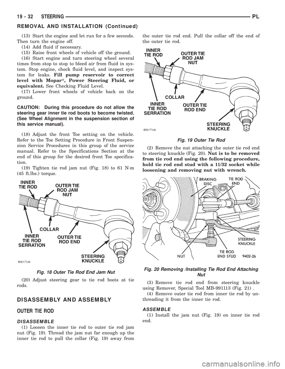
(19) Tighten tie rod jam nut (Fig. 18) to 61 N´m
(45 ft.lbs.) torque.
(20) Adjust steering gear to tie rod boots at tie
rods.
DISASSEMBLY AND ASSEMBLY
OUTER TIE ROD
DISASSEMBLE
(1) Loosen the inner tie rod to outer tie rod jam
nut (Fig. 19). Thread the jam nut far enough up the
inner tie rod to pull the collar (Fig. 19) away fromthe outer tie rod end. Pull the collar off the end of
the outer tie rod.
(2) Remove the nut attaching the outer tie rod end
to steering knuckle (Fig. 20).Nut is to be removed
from tie rod end using the following procedure,
hold tie rod end stud with a 11/32 socket while
loosening and removing nut with wrench.
(3) Remove tie rod end from steering knuckle
using Remover, Special Tool MB-991113 (Fig. 21) .
(4) Remove outer tie rod from inner tie rod by un-
threading it from the inner tie rod.
ASSEMBLE
(1) Install the jam nut (Fig. 19) on inner tie rod
end.
Fig. 18 Outer Tie Rod End Jam Nut
Fig. 19 Outer Tie Rod
Fig. 20 Removing /Installing Tie Rod End Attaching
Nut
19 - 32 STEERINGPL
REMOVAL AND INSTALLATION (Continued)
Page 934 of 1200
NOTE: Be sure the collar is installed on the inner
tie rod with the flat end of the collar against jam nut
and the open end of the collar facing the outer tie
rod end.
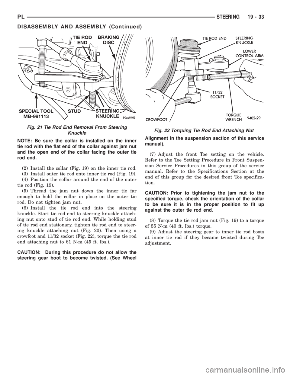
(2) Install the collar (Fig. 19) on the inner tie rod.
(3) Install outer tie rod onto inner tie rod (Fig. 19).
(4) Position the collar around the end of the outer
tie rod (Fig. 19).
(5) Thread the jam nut down the inner tie far
enough to hold the collar in place on the outer tie
rod. Do not tighten jam nut.
(6) Install the tie rod end into the steering
knuckle. Start tie rod end to steering knuckle attach-
ing nut onto stud of tie rod end. While holding stud
of tie rod end stationary, tighten tie rod end to steer-
ing knuckle attaching nut (Fig. 20). Then using a
crowfoot and 11/32 socket (Fig. 22), torque the tie rod
end attaching nut to 61 N´m (45 ft. lbs.).
CAUTION: During this procedure do not allow the
steering gear boot to become twisted. (See WheelAlignment in the suspension section of this service
manual).
(7) Adjust the front Toe setting on the vehicle.
Refer to the Toe Setting Procedure in Front Suspen-
sion Service Procedures in this group of the service
manual. Refer to the Specifications Section at the
end of this group for the desired front Toe specifica-
tion.
CAUTION: Prior to tightening the jam nut to the
specified torque, check the orientation of the collar
to be sure it is in the proper position to fit up
against the outer tie rod end.
(8) Torque the tie rod jam nut (Fig. 19) to a torque
of 55 N´m (40 ft. lbs.) torque.
(9) Adjust the steering gear to inner tie rod boots
at inner tie rod if they became twisted during Toe
adjustment.
Fig. 22 Torquing Tie Rod End Attaching NutFig. 21 Tie Rod End Removal From Steering
Knuckle
PLSTEERING 19 - 33
DISASSEMBLY AND ASSEMBLY (Continued)
Page 935 of 1200
SPECIFICATIONS
STEERING GEAR FASTENER TORQUE
SPECIFICATIONS
DESCRIPTION TORQUE
FRONT SUSPENSION CROSSMEMBER:
To Body Mounting Bolts......163 N´m (120 ft. lbs.)
STEERING GEAR:
To Crossmember Mounting Bolts .68 N´m (50 ft. lbs.)
OUTER TIE ROD:
To Steering Knuckle Nut.......55N´m(40ft.lbs.)
To Inner Tie Rod Jam Nut......61N´m(45ft.lbs.)
POWER STEERING HOSE:
Tube Nuts.................31N´m(275 in. lbs.)
Routing Bracket At Crossmember .23 N´m (17 ft. lbs.)
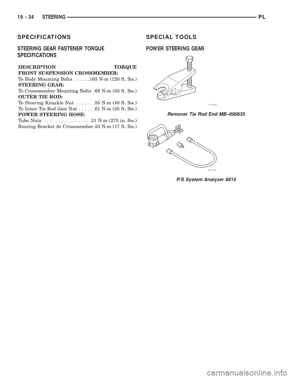
SPECIAL TOOLS
POWER STEERING GEAR
Remover Tie Rod End MB±990635
P/S System Analyzer 6815
19 - 34 STEERINGPL
Page 936 of 1200
STEERING COLUMN
INDEX
page page
DESCRIPTION AND OPERATION
STEERING COLUMN ASSEMBLY............ 35
STEERING GEAR TO STEERING
COLUMN COUPLING................... 36
DIAGNOSIS AND TESTING
STEERING COLUMN TO STEERING
GEAR COUPLING...................... 36
STEERING COLUMN..................... 36REMOVAL AND INSTALLATION
STEERING COLUMN SERVICE
PROCEDURE WARNINGS............... 37
STEERING COLUMN..................... 38
SPECIFICATIONS
STEERING COLUMN FASTEER
TORQUE SPECIFICATIONS.............. 42
DESCRIPTION AND OPERATION
STEERING COLUMN ASSEMBLY
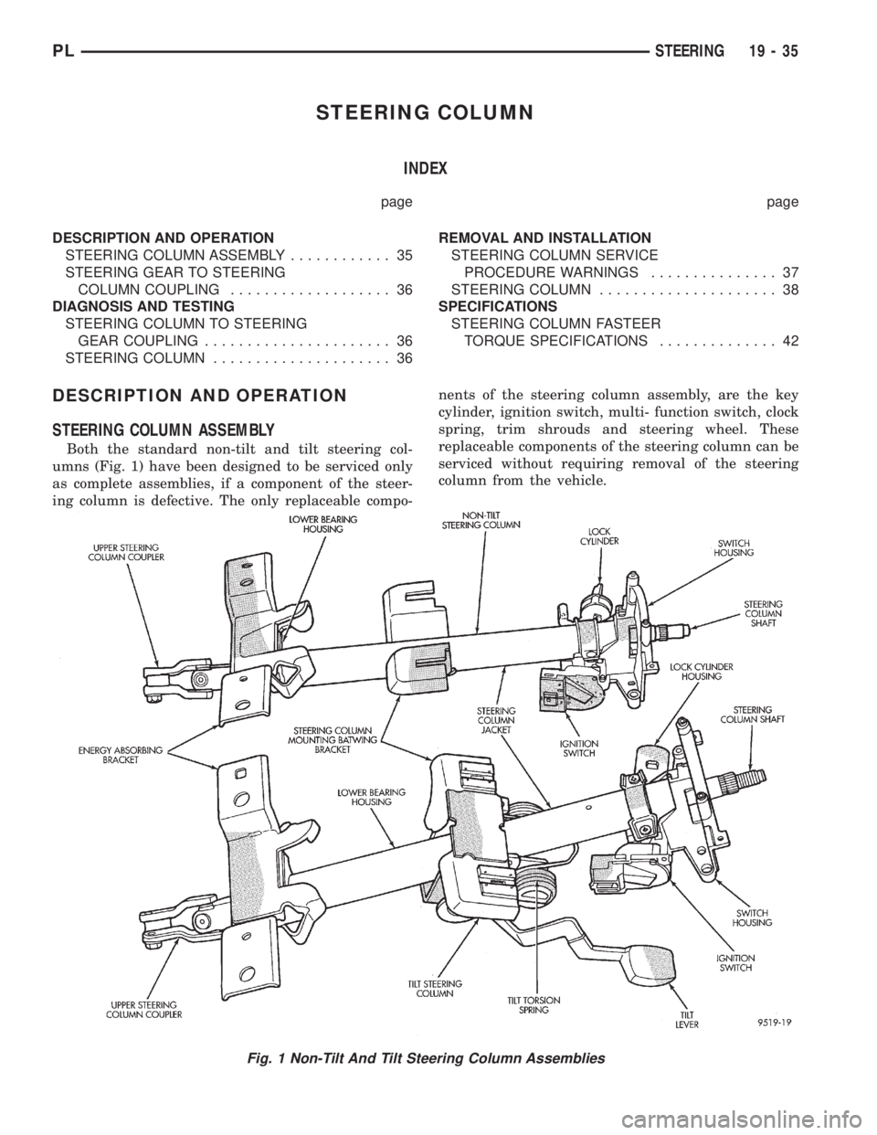
Both the standard non-tilt and tilt steering col-
umns (Fig. 1) have been designed to be serviced only
as complete assemblies, if a component of the steer-
ing column is defective. The only replaceable compo-nents of the steering column assembly, are the key
cylinder, ignition switch, multi- function switch, clock
spring, trim shrouds and steering wheel. These
replaceable components of the steering column can be
serviced without requiring removal of the steering
column from the vehicle.
Fig. 1 Non-Tilt And Tilt Steering Column Assemblies
PLSTEERING 19 - 35
Page 937 of 1200
STEERING GEAR TO STEERING COLUMN
COUPLING
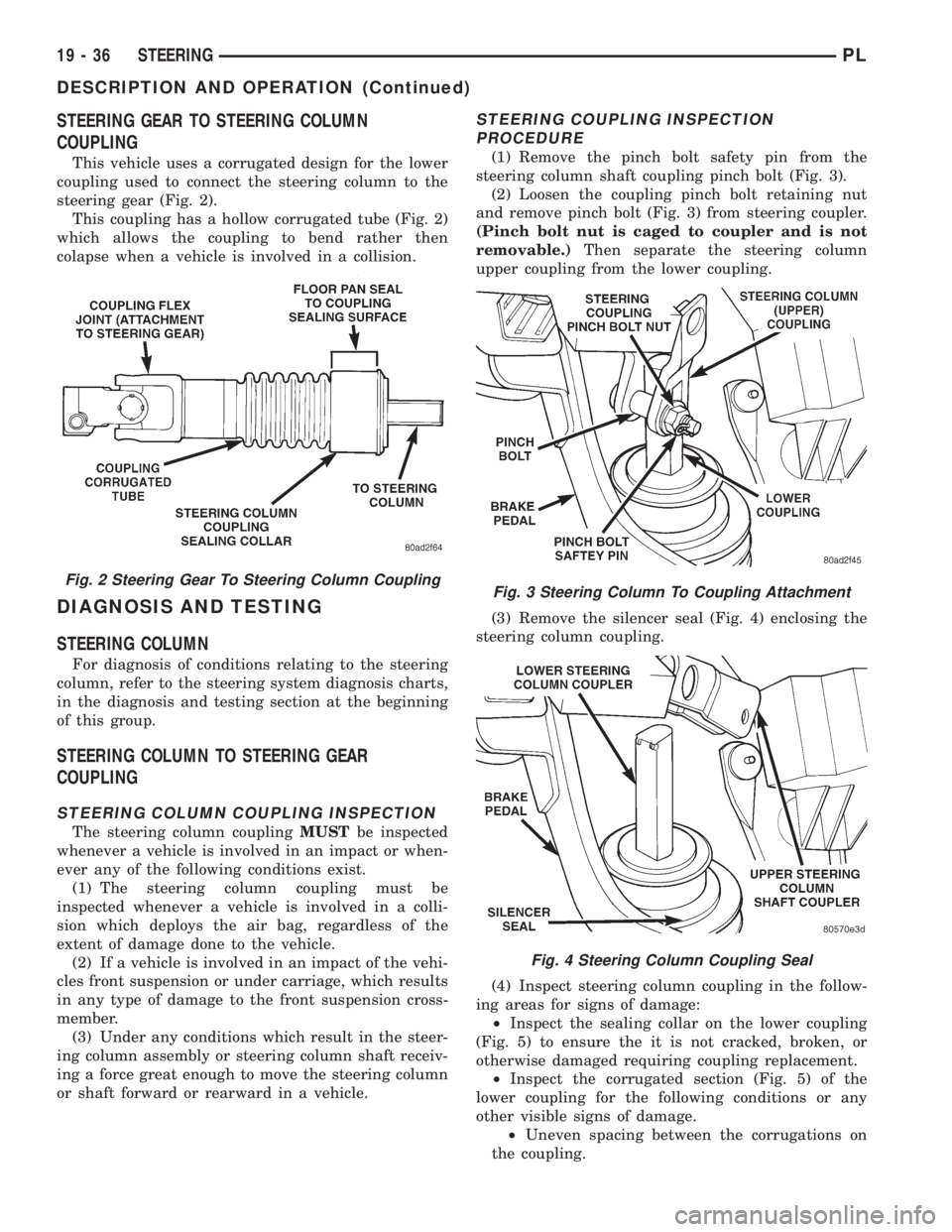
This vehicle uses a corrugated design for the lower
coupling used to connect the steering column to the
steering gear (Fig. 2).
This coupling has a hollow corrugated tube (Fig. 2)
which allows the coupling to bend rather then
colapse when a vehicle is involved in a collision.
DIAGNOSIS AND TESTING
STEERING COLUMN
For diagnosis of conditions relating to the steering
column, refer to the steering system diagnosis charts,
in the diagnosis and testing section at the beginning
of this group.
STEERING COLUMN TO STEERING GEAR
COUPLING
STEERING COLUMN COUPLING INSPECTION
The steering column couplingMUSTbe inspected
whenever a vehicle is involved in an impact or when-
ever any of the following conditions exist.
(1) The steering column coupling must be
inspected whenever a vehicle is involved in a colli-
sion which deploys the air bag, regardless of the
extent of damage done to the vehicle.
(2) If a vehicle is involved in an impact of the vehi-
cles front suspension or under carriage, which results
in any type of damage to the front suspension cross-
member.
(3) Under any conditions which result in the steer-
ing column assembly or steering column shaft receiv-
ing a force great enough to move the steering column
or shaft forward or rearward in a vehicle.
STEERING COUPLING INSPECTION
PROCEDURE
(1) Remove the pinch bolt safety pin from the
steering column shaft coupling pinch bolt (Fig. 3).
(2) Loosen the coupling pinch bolt retaining nut
and remove pinch bolt (Fig. 3) from steering coupler.
(Pinch bolt nut is caged to coupler and is not
removable.)Then separate the steering column
upper coupling from the lower coupling.
(3) Remove the silencer seal (Fig. 4) enclosing the
steering column coupling.
(4) Inspect steering column coupling in the follow-
ing areas for signs of damage:
²Inspect the sealing collar on the lower coupling
(Fig. 5) to ensure the it is not cracked, broken, or
otherwise damaged requiring coupling replacement.
²Inspect the corrugated section (Fig. 5) of the
lower coupling for the following conditions or any
other visible signs of damage.
²Uneven spacing between the corrugations on
the coupling.
Fig. 2 Steering Gear To Steering Column CouplingFig. 3 Steering Column To Coupling Attachment
Fig. 4 Steering Column Coupling Seal
19 - 36 STEERINGPL
DESCRIPTION AND OPERATION (Continued)
Page 938 of 1200
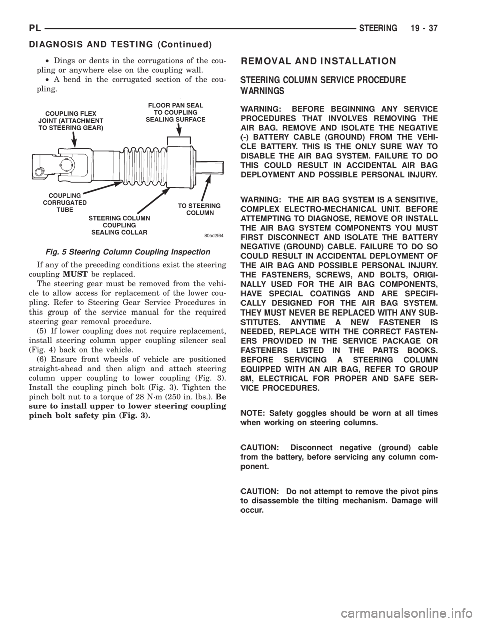
²Dings or dents in the corrugations of the cou-
pling or anywhere else on the coupling wall.
²A bend in the corrugated section of the cou-
pling.
If any of the preceding conditions exist the steering
couplingMUSTbe replaced.
The steering gear must be removed from the vehi-
cle to allow access for replacement of the lower cou-
pling. Refer to Steering Gear Service Procedures in
this group of the service manual for the required
steering gear removal procedure.
(5) If lower coupling does not require replacement,
install steering column upper coupling silencer seal
(Fig. 4) back on the vehicle.
(6) Ensure front wheels of vehicle are positioned
straight-ahead and then align and attach steering
column upper coupling to lower coupling (Fig. 3).
Install the coupling pinch bolt (Fig. 3). Tighten the
pinch bolt nut to a torque of 28 N´m (250 in. lbs.).Be
sure to install upper to lower steering coupling
pinch bolt safety pin (Fig. 3).REMOVAL AND INSTALLATION
STEERING COLUMN SERVICE PROCEDURE
WARNINGS
WARNING: BEFORE BEGINNING ANY SERVICE
PROCEDURES THAT INVOLVES REMOVING THE
AIR BAG. REMOVE AND ISOLATE THE NEGATIVE
(-) BATTERY CABLE (GROUND) FROM THE VEHI-
CLE BATTERY. THIS IS THE ONLY SURE WAY TO
DISABLE THE AIR BAG SYSTEM. FAILURE TO DO
THIS COULD RESULT IN ACCIDENTAL AIR BAG
DEPLOYMENT AND POSSIBLE PERSONAL INJURY.
WARNING: THE AIR BAG SYSTEM IS A SENSITIVE,
COMPLEX ELECTRO-MECHANICAL UNIT. BEFORE
ATTEMPTING TO DIAGNOSE, REMOVE OR INSTALL
THE AIR BAG SYSTEM COMPONENTS YOU MUST
FIRST DISCONNECT AND ISOLATE THE BATTERY
NEGATIVE (GROUND) CABLE. FAILURE TO DO SO
COULD RESULT IN ACCIDENTAL DEPLOYMENT OF
THE AIR BAG AND POSSIBLE PERSONAL INJURY.
THE FASTENERS, SCREWS, AND BOLTS, ORIGI-
NALLY USED FOR THE AIR BAG COMPONENTS,
HAVE SPECIAL COATINGS AND ARE SPECIFI-
CALLY DESIGNED FOR THE AIR BAG SYSTEM.
THEY MUST NEVER BE REPLACED WITH ANY SUB-
STITUTES. ANYTIME A NEW FASTENER IS
NEEDED, REPLACE WITH THE CORRECT FASTEN-
ERS PROVIDED IN THE SERVICE PACKAGE OR
FASTENERS LISTED IN THE PARTS BOOKS.
BEFORE SERVICING A STEERING COLUMN
EQUIPPED WITH AN AIR BAG, REFER TO GROUP
8M, ELECTRICAL FOR PROPER AND SAFE SER-
VICE PROCEDURES.
NOTE: Safety goggles should be worn at all times
when working on steering columns.
CAUTION: Disconnect negative (ground) cable
from the battery, before servicing any column com-
ponent.
CAUTION: Do not attempt to remove the pivot pins
to disassemble the tilting mechanism. Damage will
occur.
Fig. 5 Steering Column Coupling Inspection
PLSTEERING 19 - 37
DIAGNOSIS AND TESTING (Continued)
Page 939 of 1200
STEERING COLUMN
REMOVE
(1) Disconnect the negative (ground) cable from
the battery and isolate cable.
(2) Before beginning removal of steering column
assembly from vehicle, be sure front wheels of vehicle
are in thestraight aheadposition.
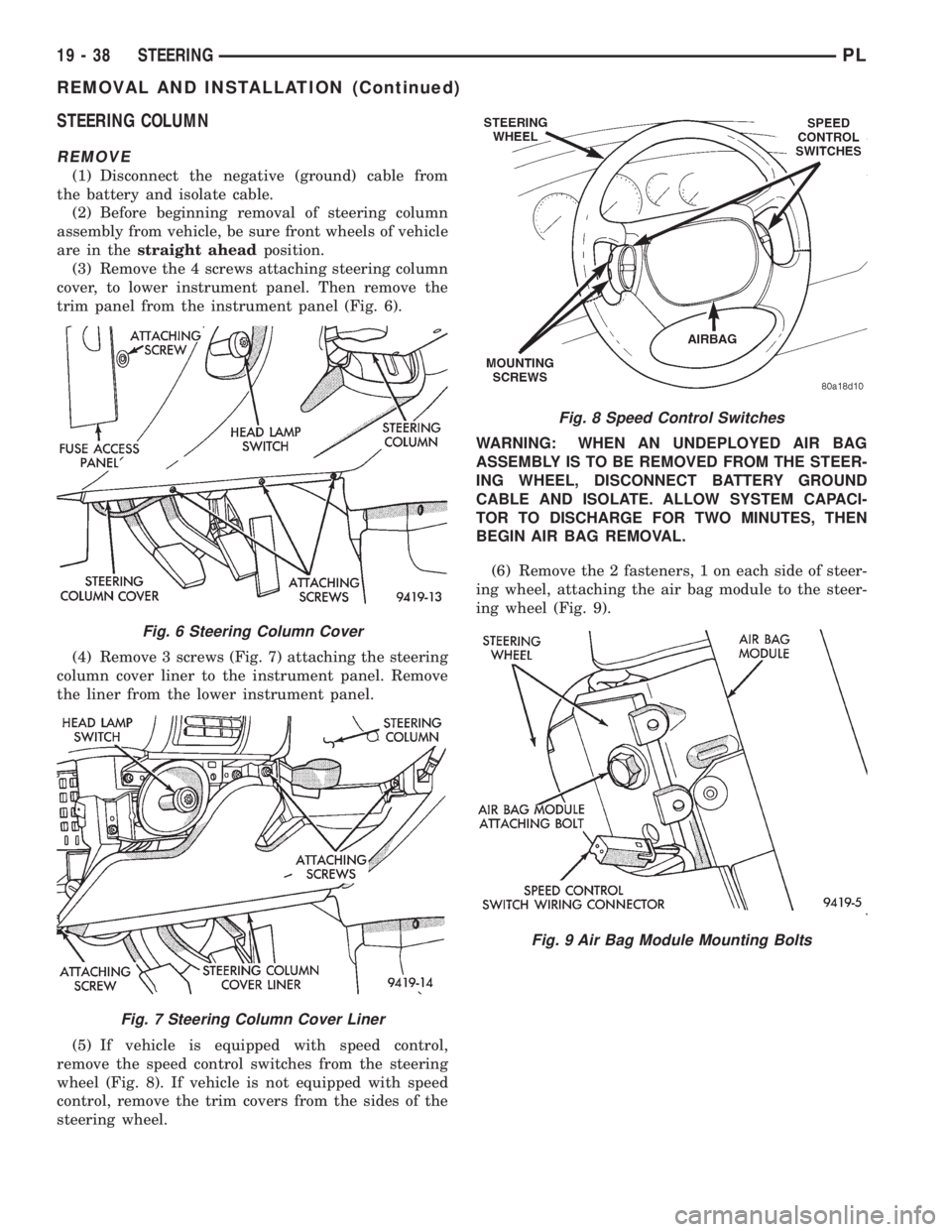
(3) Remove the 4 screws attaching steering column
cover, to lower instrument panel. Then remove the
trim panel from the instrument panel (Fig. 6).
(4) Remove 3 screws (Fig. 7) attaching the steering
column cover liner to the instrument panel. Remove
the liner from the lower instrument panel.
(5) If vehicle is equipped with speed control,
remove the speed control switches from the steering
wheel (Fig. 8). If vehicle is not equipped with speed
control, remove the trim covers from the sides of the
steering wheel.WARNING: WHEN AN UNDEPLOYED AIR BAG
ASSEMBLY IS TO BE REMOVED FROM THE STEER-
ING WHEEL, DISCONNECT BATTERY GROUND
CABLE AND ISOLATE. ALLOW SYSTEM CAPACI-
TOR TO DISCHARGE FOR TWO MINUTES, THEN
BEGIN AIR BAG REMOVAL.
(6) Remove the 2 fasteners, 1 on each side of steer-
ing wheel, attaching the air bag module to the steer-
ing wheel (Fig. 9).
Fig. 6 Steering Column Cover
Fig. 7 Steering Column Cover Liner
Fig. 8 Speed Control Switches
Fig. 9 Air Bag Module Mounting Bolts
19 - 38 STEERINGPL
REMOVAL AND INSTALLATION (Continued)
Page 940 of 1200
WARNING: WHEN HANDLING AN UNDEPLOYED
AIR BAG MODULE DURING SERVICING OF THE
STEERING COLUMN THE FOLLOWING PRECAU-
TIONS SHOULD BE OBSERVED. AT NO TIME
SHOULD ANY SOURCE OF ELECTRICITY BE PER-
MITTED NEAR THE INFLATOR ON THE BACK OF
THE AIR BAG MODULE. WHEN CARRYING A LIVE
MODULE, THE TRIM COVER SHOULD BE POINTED
AWAY FROM THE BODY TO MINIMIZE INJURY IF
MODULE ACCIDENTLY DEPLOYS. IF AIR BAG MOD-
ULE IS PLACED ON A BENCH OR OTHER SUR-
FACE, PLASTIC COVER SHOULD BE FACE UP TO
MINIMIZE MOVEMENT IN CASE OF ACCIDENTAL
DEPLOYMENT.
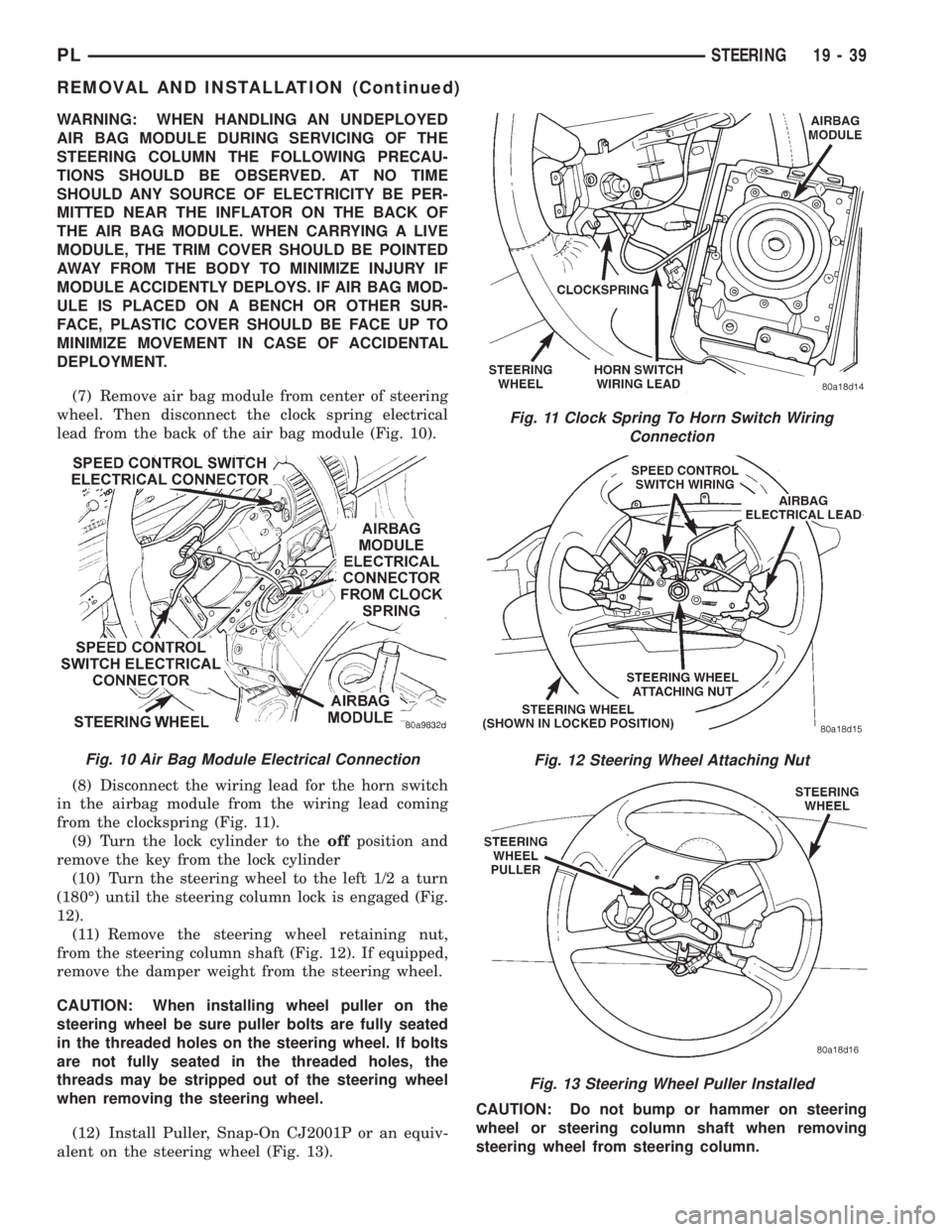
(7) Remove air bag module from center of steering
wheel. Then disconnect the clock spring electrical
lead from the back of the air bag module (Fig. 10).
(8) Disconnect the wiring lead for the horn switch
in the airbag module from the wiring lead coming
from the clockspring (Fig. 11).
(9) Turn the lock cylinder to theoffposition and
remove the key from the lock cylinder
(10) Turn the steering wheel to the left 1/2 a turn
(180É) until the steering column lock is engaged (Fig.
12).
(11) Remove the steering wheel retaining nut,
from the steering column shaft (Fig. 12). If equipped,
remove the damper weight from the steering wheel.
CAUTION: When installing wheel puller on the
steering wheel be sure puller bolts are fully seated
in the threaded holes on the steering wheel. If bolts
are not fully seated in the threaded holes, the
threads may be stripped out of the steering wheel
when removing the steering wheel.
(12) Install Puller, Snap-On CJ2001P or an equiv-
alent on the steering wheel (Fig. 13).CAUTION: Do not bump or hammer on steering
wheel or steering column shaft when removing
steering wheel from steering column.
Fig. 11 Clock Spring To Horn Switch Wiring
Connection
Fig. 12 Steering Wheel Attaching Nut
Fig. 13 Steering Wheel Puller Installed
Fig. 10 Air Bag Module Electrical Connection
PLSTEERING 19 - 39
REMOVAL AND INSTALLATION (Continued)