DODGE NEON 1999 Service Repair Manual
Manufacturer: DODGE, Model Year: 1999, Model line: NEON, Model: DODGE NEON 1999Pages: 1200, PDF Size: 35.29 MB
Page 941 of 1200
(13) Remove steering wheel assembly from steer-
ing column shaft using Puller, Special Tool C-3428-B
or equivalent.
(14) Remove key lock cylinder from steering col-
umn. Key lock cylinder is removed from steering col-
umn using the following procedure. Place the key
lock cylinder in the Run position. Then through the
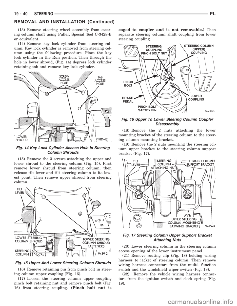
hole in lower shroud, (Fig. 14) depress lock cylinder
retaining tab and remove key lock cylinder.
(15) Remove the 3 screws attaching the upper and
lower shroud to the steering column (Fig. 15). First
remove lower shroud from steering column, then
release tilt lever and tilt steering column to its low-
est point. Then remove upper shroud from steering
column.
(16) Remove retaining pin from pinch bolt in steer-
ing column upper coupling (Fig. 16).
(17) Loosen the steering column upper coupling
pinch bolt retaining nut and remove pinch bolt (Fig.
16) from steering coupling.(Pinch bolt nut iscaged to coupler and is not removable.)Then
separate steering column shaft coupling from lower
steering coupling.
(18) Remove the 2 nuts attaching the lower
mounting bracket of the steering column to the steer-
ing column mounting bracket.
(19) Remove the 2 nuts mounting the steering col-
umn upper bracket to the steering column support
bracket (Fig. 17).
(20) Lower steering column in the steering column
access opening of the lower instrument panel.
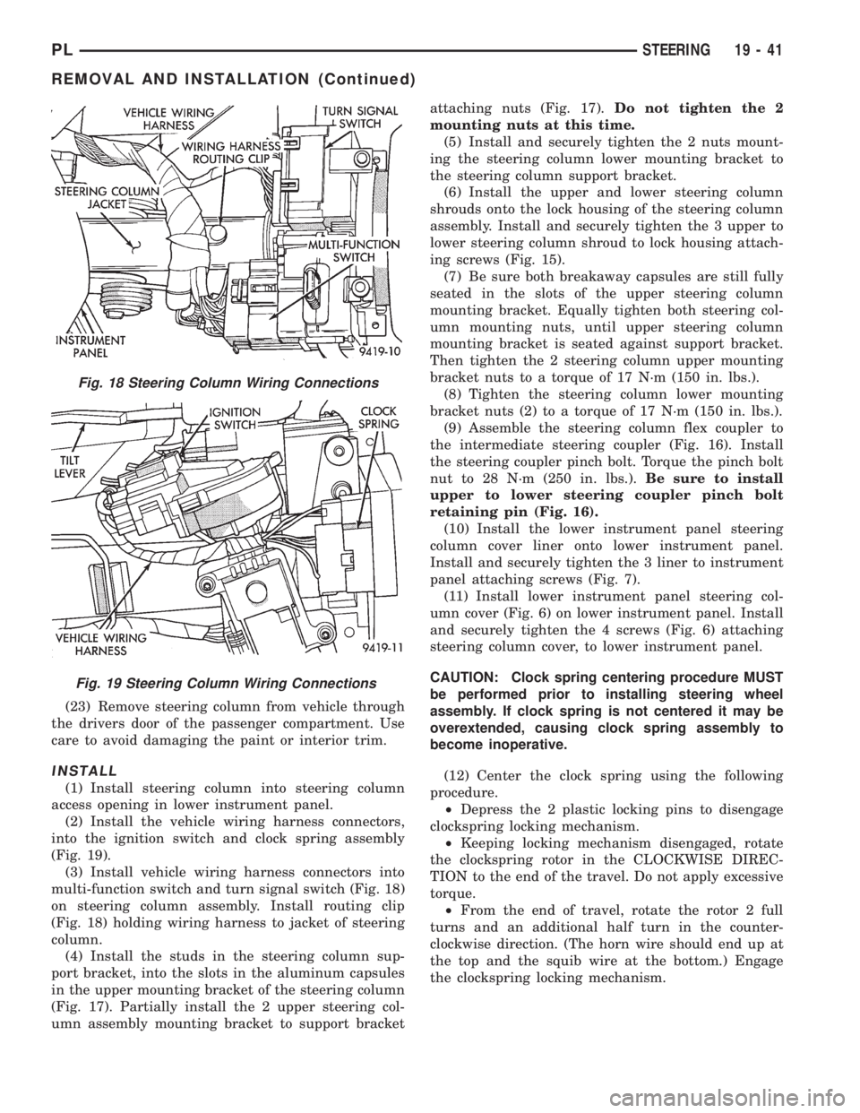
(21) Remove routing clip (Fig. 18) holding wiring
harness to jacket of steering column. Then remove
wiring harness connectors from the multi- function
switch and the windshield wiper switch (Fig. 18).
(22) Remove the vehicle wiring harness connec-
tors from the ignition switch and clock spring (Fig.
19).
Fig. 14 Key Lock Cylinder Access Hole In Steering
Column Shrouds
Fig. 15 Upper And Lower Steering Column Shrouds
Fig. 16 Upper To Lower Steering Column Coupler
Disassembly
Fig. 17 Steering Column Upper Support Bracket
Attaching Nuts
19 - 40 STEERINGPL
REMOVAL AND INSTALLATION (Continued)
Page 942 of 1200
(23) Remove steering column from vehicle through
the drivers door of the passenger compartment. Use
care to avoid damaging the paint or interior trim.
INSTALL
(1) Install steering column into steering column
access opening in lower instrument panel.
(2) Install the vehicle wiring harness connectors,
into the ignition switch and clock spring assembly
(Fig. 19).
(3) Install vehicle wiring harness connectors into
multi-function switch and turn signal switch (Fig. 18)
on steering column assembly. Install routing clip
(Fig. 18) holding wiring harness to jacket of steering
column.
(4) Install the studs in the steering column sup-
port bracket, into the slots in the aluminum capsules
in the upper mounting bracket of the steering column
(Fig. 17). Partially install the 2 upper steering col-
umn assembly mounting bracket to support bracketattaching nuts (Fig. 17).Do not tighten the 2
mounting nuts at this time.
(5) Install and securely tighten the 2 nuts mount-
ing the steering column lower mounting bracket to
the steering column support bracket.
(6) Install the upper and lower steering column
shrouds onto the lock housing of the steering column
assembly. Install and securely tighten the 3 upper to
lower steering column shroud to lock housing attach-
ing screws (Fig. 15).
(7) Be sure both breakaway capsules are still fully
seated in the slots of the upper steering column
mounting bracket. Equally tighten both steering col-
umn mounting nuts, until upper steering column
mounting bracket is seated against support bracket.
Then tighten the 2 steering column upper mounting
bracket nuts to a torque of 17 N´m (150 in. lbs.).
(8) Tighten the steering column lower mounting
bracket nuts (2) to a torque of 17 N´m (150 in. lbs.).
(9) Assemble the steering column flex coupler to
the intermediate steering coupler (Fig. 16). Install
the steering coupler pinch bolt. Torque the pinch bolt
nut to 28 N´m (250 in. lbs.).Be sure to install
upper to lower steering coupler pinch bolt
retaining pin (Fig. 16).
(10) Install the lower instrument panel steering
column cover liner onto lower instrument panel.
Install and securely tighten the 3 liner to instrument
panel attaching screws (Fig. 7).
(11) Install lower instrument panel steering col-
umn cover (Fig. 6) on lower instrument panel. Install
and securely tighten the 4 screws (Fig. 6) attaching
steering column cover, to lower instrument panel.
CAUTION: Clock spring centering procedure MUST
be performed prior to installing steering wheel
assembly. If clock spring is not centered it may be
overextended, causing clock spring assembly to
become inoperative.
(12) Center the clock spring using the following
procedure.
²Depress the 2 plastic locking pins to disengage
clockspring locking mechanism.
²Keeping locking mechanism disengaged, rotate
the clockspring rotor in the CLOCKWISE DIREC-
TION to the end of the travel. Do not apply excessive
torque.
²From the end of travel, rotate the rotor 2 full
turns and an additional half turn in the counter-
clockwise direction. (The horn wire should end up at
the top and the squib wire at the bottom.) Engage
the clockspring locking mechanism.
Fig. 18 Steering Column Wiring Connections
Fig. 19 Steering Column Wiring Connections
PLSTEERING 19 - 41
REMOVAL AND INSTALLATION (Continued)
Page 943 of 1200
CAUTION: Do not install steering wheel onto shaft
of steering column assembly by driving it onto the
shaft. Pull steering wheel down onto steering col-
umn shaft using ONLY the steering wheel retaining
nut.
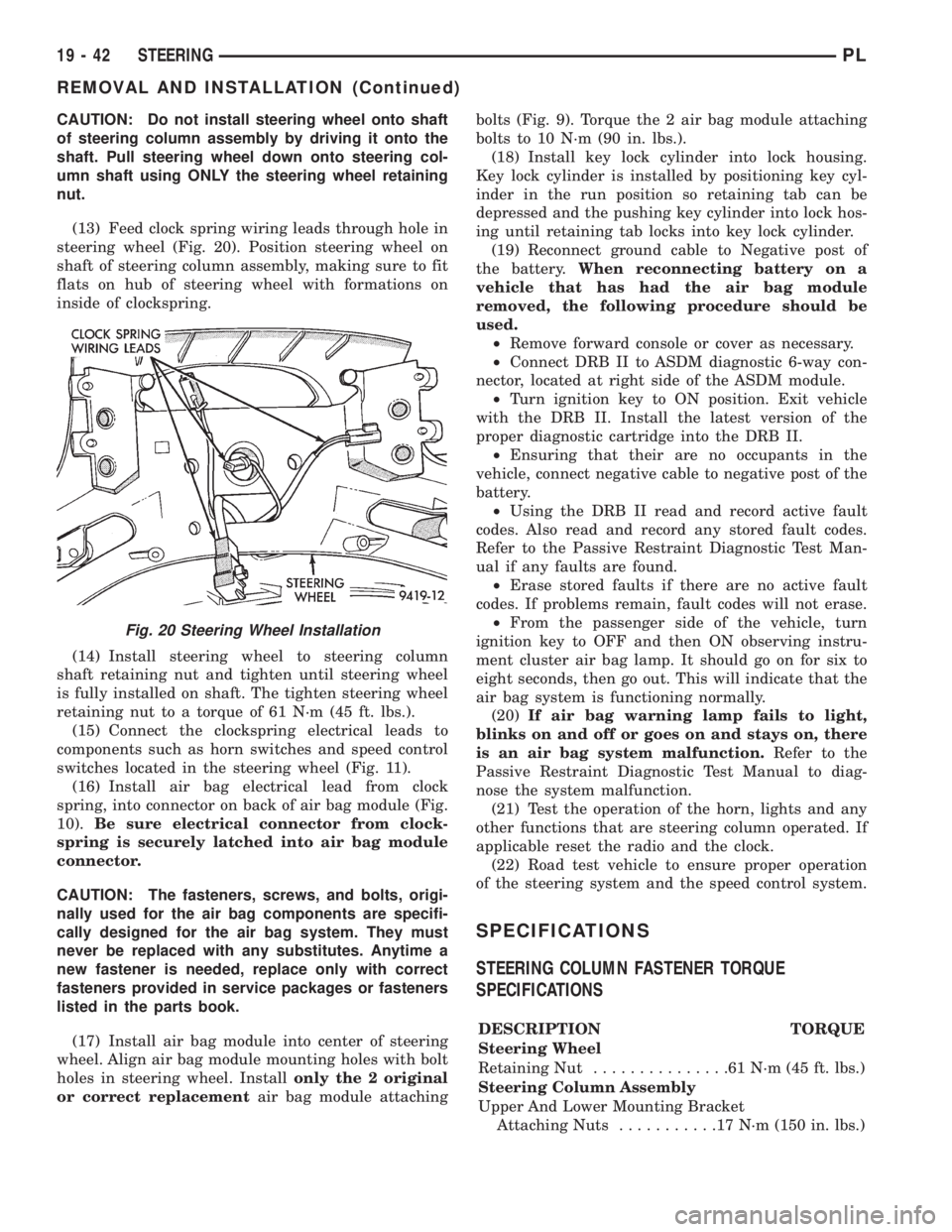
(13) Feed clock spring wiring leads through hole in
steering wheel (Fig. 20). Position steering wheel on
shaft of steering column assembly, making sure to fit
flats on hub of steering wheel with formations on
inside of clockspring.
(14) Install steering wheel to steering column
shaft retaining nut and tighten until steering wheel
is fully installed on shaft. The tighten steering wheel
retaining nut to a torque of 61 N´m (45 ft. lbs.).
(15) Connect the clockspring electrical leads to
components such as horn switches and speed control
switches located in the steering wheel (Fig. 11).
(16) Install air bag electrical lead from clock
spring, into connector on back of air bag module (Fig.
10).Be sure electrical connector from clock-
spring is securely latched into air bag module
connector.
CAUTION: The fasteners, screws, and bolts, origi-
nally used for the air bag components are specifi-
cally designed for the air bag system. They must
never be replaced with any substitutes. Anytime a
new fastener is needed, replace only with correct
fasteners provided in service packages or fasteners
listed in the parts book.
(17) Install air bag module into center of steering
wheel. Align air bag module mounting holes with bolt
holes in steering wheel. Installonly the 2 original
or correct replacementair bag module attachingbolts (Fig. 9). Torque the 2 air bag module attaching
bolts to 10 N´m (90 in. lbs.).
(18) Install key lock cylinder into lock housing.
Key lock cylinder is installed by positioning key cyl-
inder in the run position so retaining tab can be
depressed and the pushing key cylinder into lock hos-
ing until retaining tab locks into key lock cylinder.
(19) Reconnect ground cable to Negative post of
the battery.When reconnecting battery on a
vehicle that has had the air bag module
removed, the following procedure should be
used.
²Remove forward console or cover as necessary.
²Connect DRB II to ASDM diagnostic 6-way con-
nector, located at right side of the ASDM module.
²Turn ignition key to ON position. Exit vehicle
with the DRB II. Install the latest version of the
proper diagnostic cartridge into the DRB II.
²Ensuring that their are no occupants in the
vehicle, connect negative cable to negative post of the
battery.
²Using the DRB II read and record active fault
codes. Also read and record any stored fault codes.
Refer to the Passive Restraint Diagnostic Test Man-
ual if any faults are found.
²Erase stored faults if there are no active fault
codes. If problems remain, fault codes will not erase.
²From the passenger side of the vehicle, turn
ignition key to OFF and then ON observing instru-
ment cluster air bag lamp. It should go on for six to
eight seconds, then go out. This will indicate that the
air bag system is functioning normally.
(20)If air bag warning lamp fails to light,
blinks on and off or goes on and stays on, there
is an air bag system malfunction.Refer to the
Passive Restraint Diagnostic Test Manual to diag-
nose the system malfunction.
(21) Test the operation of the horn, lights and any
other functions that are steering column operated. If
applicable reset the radio and the clock.
(22) Road test vehicle to ensure proper operation
of the steering system and the speed control system.
SPECIFICATIONS
STEERING COLUMN FASTENER TORQUE
SPECIFICATIONS
DESCRIPTION TORQUE
Steering Wheel
Retaining Nut...............61N´m(45ft.lbs.)
Steering Column Assembly
Upper And Lower Mounting Bracket
Attaching Nuts...........17N´m(150 in. lbs.)
Fig. 20 Steering Wheel Installation
19 - 42 STEERINGPL
REMOVAL AND INSTALLATION (Continued)
Page 944 of 1200
TRANSAXLE
CONTENTS
page page
31TH AUTOMATIC TRANSAXLE............. 40 NVT350 (A-578) MANUAL TRANSAXLE....... 1
NV T350 (A-578) MANUAL TRANSAXLE
INDEX
page page
GENERAL INFORMATION
GEAR RATIOS........................... 2
GEARSHIFT PATTERN..................... 2
NV T350 MANUAL TRANSAXLE.............. 1
SEALANTS.............................. 2
SELECTION OF LUBRICANT................ 2
SPECIAL ADDITIVES...................... 2
TRANSAXLE IDENTIFICATION INFORMATION . . . 2
DESCRIPTION AND OPERATION
AXLE SEALS............................ 3
SHIFT LEVERS.......................... 3
DIAGNOSIS AND TESTING
CLUTCH PROBLEMS...................... 3
COMMON PROBLEM CAUSES.............. 3
HARD SHIFTING......................... 3
LOW LUBRICANT LEVEL................... 3
NOISY OPERATION....................... 3
SLIPS OUT OF GEAR..................... 3
SERVICE PROCEDURES
FLUID DRAIN AND FILL.................... 3
REMOVAL AND INSTALLATION
AXLE SEALS............................ 8
BACK-UP LAMP SWITCH................... 7
CROSSOVER LEVER...................... 7
GEARSHIFT BOOT....................... 4
GEARSHIFT CABLES...................... 4GEARSHIFT KNOB....................... 4
GEARSHIFT MECHANISM REPLACEMENT..... 6
SELECTOR LEVER....................... 8
SHIFT SHAFT SEALS...................... 8
TRANSAXLE............................ 8
VEHICLE SPEED SENSOR DRIVE GEAR...... 7
DISASSEMBLY AND ASSEMBLY
DIFFERENTIAL......................... 24
INPUT SHAFT.......................... 20
OUTPUT SHAFT........................ 24
SHIFT RAILS OVERHAUL................. 29
SYNCHRONIZER........................ 29
TRANSAXLE CASE OVERHAUL............. 30
TRANSAXLE........................... 10
CLEANING AND INSPECTION
SYNCHRONIZER........................ 35
TRANSAXLE........................... 35
ADJUSTMENTS
BEARING ADJUSTMENT PROCEDURE....... 35
DIFFERENTIAL BEARING PRELOAD
ADJUSTMENT......................... 36
GEARSHIFT CROSSOVER CABLE........... 35
SPECIFICATIONS
NV T350 (A-578) SPECIFICATIONS.......... 37
SPECIAL TOOLS
NV T350 (A-578) MANUAL TRANSAXLE....... 37
GENERAL INFORMATION
NV T350 MANUAL TRANSAXLE
NOTE: Safety goggles should be worn at all times
when working on these transaxles.
This five speed is a constant-mesh manual tran-
saxle. All gear ranges, except reverse, are synchro-
nized. The reverse gear utilizes a brake and blockingring for shifting ease. The reverse idler gear is sup-
ported on a sliding spindle idler shaft. The transaxle
case is aluminum with a steel end±plate bearing
cover. It is housed in a die-cast aluminum case fea-
turing a two±piece, middle split design.
The NV T350 (A-578) transaxle internal compo-
nents can be serviced only by separating the gear
case from the bellhousing case.
PLTRANSAXLE 21 - 1
Page 945 of 1200
CAUTION: The transaxle output shaft is serviced as
a unit. No disassembly and reassembly is possible.
Damage to the transaxle may result.
TRANSAXLE IDENTIFICATION INFORMATION
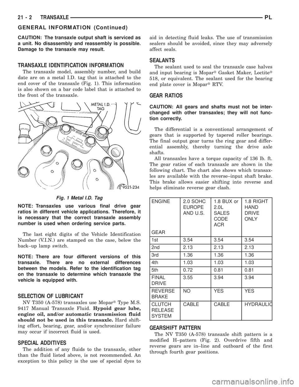
The transaxle model, assembly number, and build
date are on a metal I.D. tag that is attached to the
end cover of the transaxle (Fig. 1). This information
is also shown on a bar code label that is attached to
the front of the transaxle.
NOTE: Transaxles use various final drive gear
ratios in different vehicle applications. Therefore, it
is necessary that the correct transaxle assembly
number is used when ordering service parts.
The last eight digits of the Vehicle Identification
Number (V.I.N.) are stamped on the case, below the
back±up lamp switch.
NOTE: There are four different versions of this
transaxle. There are no external differences
between the models. Refer to the identification tag
on the transaxle to determine which transaxle the
vehicle is equipped with.
SELECTION OF LUBRICANT
NV T350 (A-578) transaxles use MopartType M.S.
9417 Manual Transaxle Fluid.Hypoid gear lube,
engine oil, and/or automatic transmission fluid
should not be used in this transaxle.Hard shift-
ing effort, bearing, gear, and/or synchronizer failure
may occur if incorrect fluid is used.
SPECIAL ADDITIVES
The addition of any fluids to the transaxle, other
than the fluid listed above, is not recommended. An
exception to this policy is the use of special dyes toaid in detecting fluid leaks. The use of transmission
sealers should be avoided, since they may adversely
affect seals.
SEALANTS
The sealant used to seal the transaxle case halves
and input bearing is MopartGasket Maker, Loctitet
518, or equivalent. The sealant used for the bearing
end plate cover is MopartRTV.
GEAR RATIOS
CAUTION: All gears and shafts must not be inter-
changed with other transaxles; they will not func-
tion correctly.
The differential is a conventional arrangement of
gears that is supported by tapered roller bearings.
The final output gear turns the ring gear and differ-
ential assembly, thereby turning the drive axle
shafts.
All transaxles have a torque capacity of 136 lb. ft.
The gear ratios of each transaxle are shown in the
following chart. The chart also shows which transax-
les are available with the reverse±input shaft brake.
This brake allows easier shifting into reverse and
helps eliminate reverse gear clash.
ENGINE 2.0 SOHC
EUROPE
AND U.S.1.8 BUX or
2.0L
SALES
CODE
ACR1.8 RIGHT
HAND
DRIVE
ONLY
GEAR
1st 3.54 3.54 3.54
2nd 2.13 2.13 2.13
3rd 1.36 1.36 1.36
4th 1.03 1.03 1.03
5th 0.72 0.81 0.81
FINAL
DRIVE3.55 3.94 3.94
REVERSE
BRAKENO YES YES
CLUTCH
RELEASE
SYSTEMCABLE CABLE HYDRAULIC
GEARSHIFT PATTERN
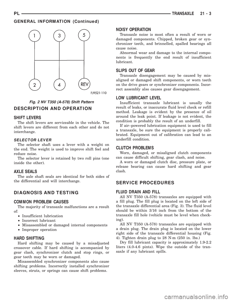
The NV T350 (A-578) transaxle shift pattern is a
modified H±pattern (Fig. 2). Overdrive fifth and
reverse gears are in±line and outboard of the first
through fourth gear positions.
Fig. 1 Metal I.D. Tag
21 - 2 TRANSAXLEPL
GENERAL INFORMATION (Continued)
Page 946 of 1200
DESCRIPTION AND OPERATION
SHIFT LEVERS
The shift levers are serviceable in the vehicle. The
shift levers are different from each other and do not
interchange.
SELECTOR LEVER
The selector shaft uses a lever with a weight on
the end. The weight is used to improve shift feel and
reduce noise.
The selector lever is retained by two roll pins (one
inside the other).
AXLE SEALS
The axle shaft seals are identical for both sides of
the differential and will interchange.
DIAGNOSIS AND TESTING
COMMON PROBLEM CAUSES
The majority of transaxle malfunctions are a result
of:
²Insufficient lubrication
²Incorrect lubricant
²Misassembled or damaged internal components
²Improper operation
HARD SHIFTING
Hard shifting may be caused by a misadjusted
crossover cable. If hard shifting is accompanied by
gear clash, synchronizer clutch and stop rings, or
gear teeth may be worn or damaged.
Misassembled synchronizer components also cause
shifting problems. Incorrectly installed synchronizer
sleeves, struts, or springs can cause shift problems.
NOISY OPERATION
Transaxle noise is most often a result of worn or
damaged components. Chipped, broken gear or syn-
chronizer teeth, and brinnelled, spalled bearings all
cause noise.
Abnormal wear and damage to the internal compo-
nents is frequently the end result of insufficient
lubricant.
SLIPS OUT OF GEAR
Transaxle disengagement may be caused by mis-
aligned or damaged shift components, or worn teeth
on the drive gears or synchronizer components. Incor-
rect assembly also causes gear disengagement.
LOW LUBRICANT LEVEL
Insufficient transaxle lubricant is usually the
result of leaks, or inaccurate fluid level check or refill
method. Leakage is evident by the presence of oil
around the leak point. If leakage is not evident, the
condition is probably the result of an underfill.
If air±powered lubrication equipment is used to fill
a transaxle, be sure the equipment is properly cali-
brated. Equipment out of calibration can lead to an
underfill condition.
CLUTCH PROBLEMS
Worn, damaged, or misaligned clutch components
can cause difficult shifting, gear clash, and noise.
A worn or damaged clutch disc, pressure plate, or
release bearing can cause hard shifting and gear
clash.
SERVICE PROCEDURES
FLUID DRAIN AND FILL
All NV T350 (A-578) transaxles are equipped with
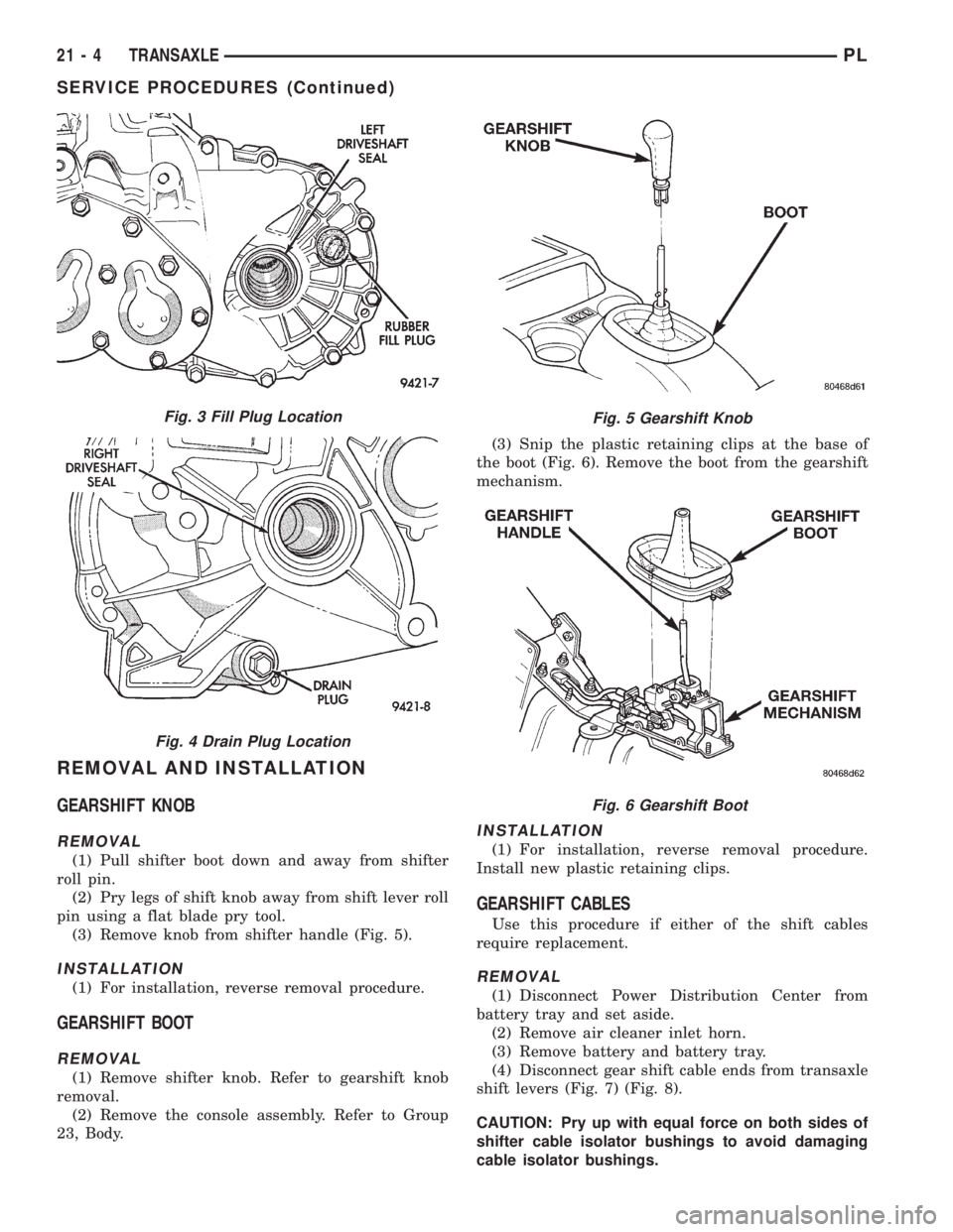
a fill plug. The fill plug is located on the left side of
the transaxle differential area (Fig. 3). The fluid level
should be within 3/16 inch from the bottom of the
transaxle fill hole (vehicle must be level when check-
ing).
All NV T350 (A-578) transaxles are equipped with
a drain plug. The drain plug is located on the lower
right side of the transaxle differential housing (Fig.
4). Tighten drain plug to 28 N´m (250 in. lbs.)
Dry fill lubricant capacity is approximately 1.9-2.2
liters (4.0-4.6 pints). Wipe the outside of the tran-
saxle if any lubricant spills.
Fig. 2 NV T350 (A-578) Shift Pattern
PLTRANSAXLE 21 - 3
GENERAL INFORMATION (Continued)
Page 947 of 1200
REMOVAL AND INSTALLATION
GEARSHIFT KNOB
REMOVAL
(1) Pull shifter boot down and away from shifter
roll pin.
(2) Pry legs of shift knob away from shift lever roll
pin using a flat blade pry tool.
(3) Remove knob from shifter handle (Fig. 5).
INSTALLATION
(1) For installation, reverse removal procedure.
GEARSHIFT BOOT
REMOVAL
(1) Remove shifter knob. Refer to gearshift knob
removal.
(2) Remove the console assembly. Refer to Group
23, Body.(3) Snip the plastic retaining clips at the base of
the boot (Fig. 6). Remove the boot from the gearshift
mechanism.
INSTALLATION
(1) For installation, reverse removal procedure.
Install new plastic retaining clips.
GEARSHIFT CABLES
Use this procedure if either of the shift cables
require replacement.
REMOVAL
(1) Disconnect Power Distribution Center from
battery tray and set aside.
(2) Remove air cleaner inlet horn.
(3) Remove battery and battery tray.
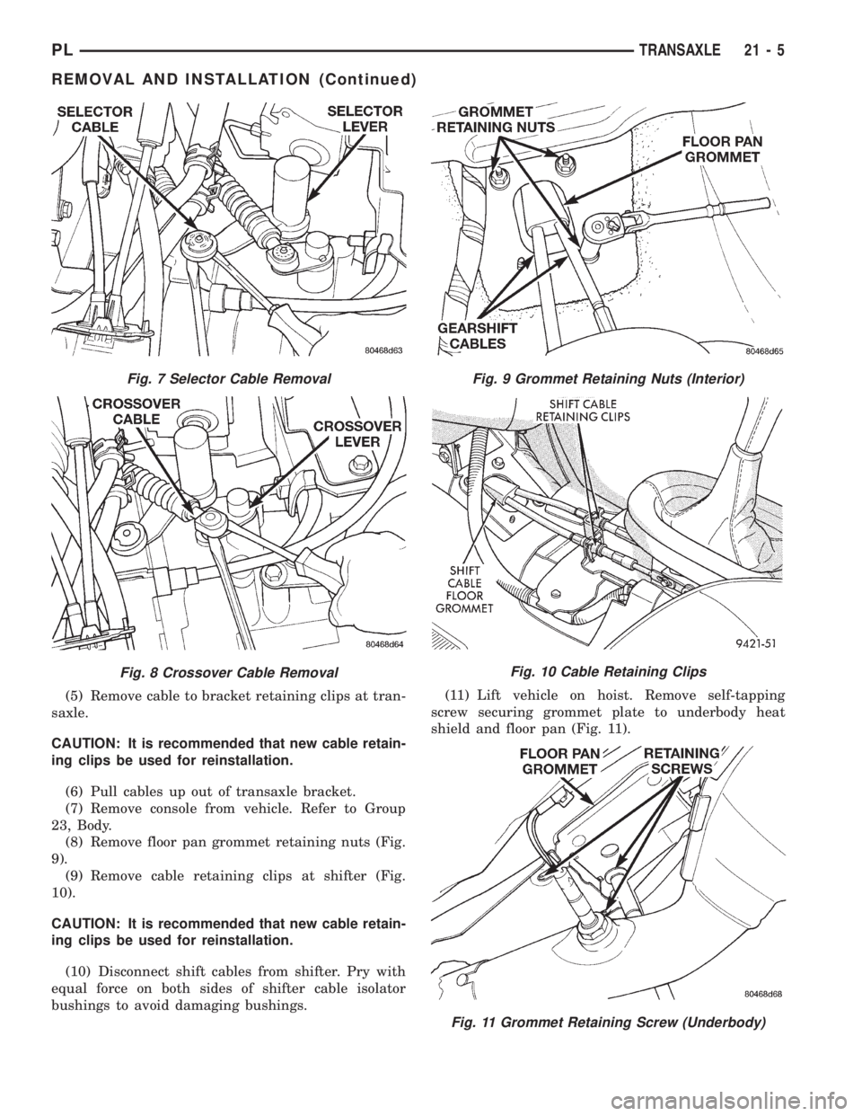
(4) Disconnect gear shift cable ends from transaxle
shift levers (Fig. 7) (Fig. 8).
CAUTION: Pry up with equal force on both sides of
shifter cable isolator bushings to avoid damaging
cable isolator bushings.
Fig. 5 Gearshift Knob
Fig. 6 Gearshift Boot
Fig. 3 Fill Plug Location
Fig. 4 Drain Plug Location
21 - 4 TRANSAXLEPL
SERVICE PROCEDURES (Continued)
Page 948 of 1200
(5) Remove cable to bracket retaining clips at tran-
saxle.
CAUTION: It is recommended that new cable retain-
ing clips be used for reinstallation.
(6) Pull cables up out of transaxle bracket.
(7) Remove console from vehicle. Refer to Group
23, Body.
(8) Remove floor pan grommet retaining nuts (Fig.
9).
(9) Remove cable retaining clips at shifter (Fig.
10).
CAUTION: It is recommended that new cable retain-
ing clips be used for reinstallation.
(10) Disconnect shift cables from shifter. Pry with
equal force on both sides of shifter cable isolator
bushings to avoid damaging bushings.(11) Lift vehicle on hoist. Remove self-tapping
screw securing grommet plate to underbody heat
shield and floor pan (Fig. 11).
Fig. 7 Selector Cable Removal
Fig. 8 Crossover Cable Removal
Fig. 9 Grommet Retaining Nuts (Interior)
Fig. 10 Cable Retaining Clips
Fig. 11 Grommet Retaining Screw (Underbody)
PLTRANSAXLE 21 - 5
REMOVAL AND INSTALLATION (Continued)
Page 949 of 1200
(12) Detach cables from cable support clip in tun-
nel above exhaust catalyst.
(13) Remove shift cable assembly from vehicle.
INSTALLATION
CAUTION: Gearshift cable bushings must not be
lubricated or the bushings will swell and split.
(1) To install, reverse removal procedure. After
cables have been replaced, cable adjustment should
be checked. Refer to cable adjustment procedure in
this section.
CAUTION: Only the crossover cable is adjustable.
The selector cable does not have any adjustment
capabilities.
GEARSHIFT CROSSOVER CABLE
ADJUSTMENT
(1) Remove shift console from vehicle.
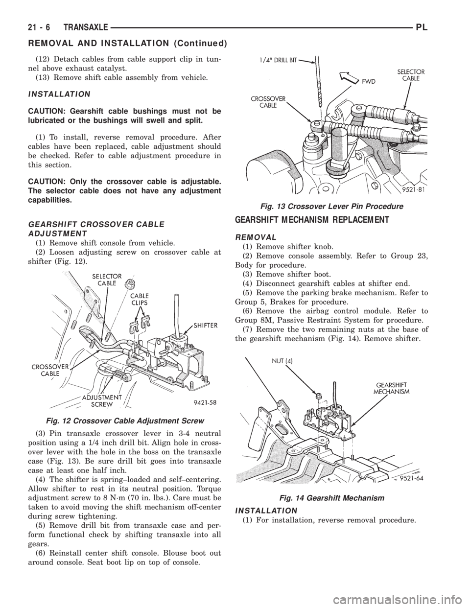
(2) Loosen adjusting screw on crossover cable at
shifter (Fig. 12).
(3) Pin transaxle crossover lever in 3-4 neutral
position using a 1/4 inch drill bit. Align hole in cross-
over lever with the hole in the boss on the transaxle
case (Fig. 13). Be sure drill bit goes into transaxle
case at least one half inch.
(4) The shifter is spring±loaded and self±centering.
Allow shifter to rest in its neutral position. Torque
adjustment screw to 8 N´m (70 in. lbs.). Care must be
taken to avoid moving the shift mechanism off-center
during screw tightening.
(5) Remove drill bit from transaxle case and per-
form functional check by shifting transaxle into all
gears.
(6) Reinstall center shift console. Blouse boot out
around console. Seat boot lip on top of console.
GEARSHIFT MECHANISM REPLACEMENT
REMOVAL
(1) Remove shifter knob.
(2) Remove console assembly. Refer to Group 23,
Body for procedure.
(3) Remove shifter boot.
(4) Disconnect gearshift cables at shifter end.
(5) Remove the parking brake mechanism. Refer to
Group 5, Brakes for procedure.
(6) Remove the airbag control module. Refer to
Group 8M, Passive Restraint System for procedure.
(7) Remove the two remaining nuts at the base of
the gearshift mechanism (Fig. 14). Remove shifter.
INSTALLATION
(1) For installation, reverse removal procedure.
Fig. 12 Crossover Cable Adjustment Screw
Fig. 13 Crossover Lever Pin Procedure
Fig. 14 Gearshift Mechanism
21 - 6 TRANSAXLEPL
REMOVAL AND INSTALLATION (Continued)
Page 950 of 1200
VEHICLE SPEED SENSOR DRIVE GEAR
REMOVAL
(1) Raise vehicle on hoist.
(2) Remove wiring connector from speed sensor.
CAUTION: Clean area around speed sensor before
removing. This prevents the possibility of dirt from
entering the transaxle during speed sensor
removal.
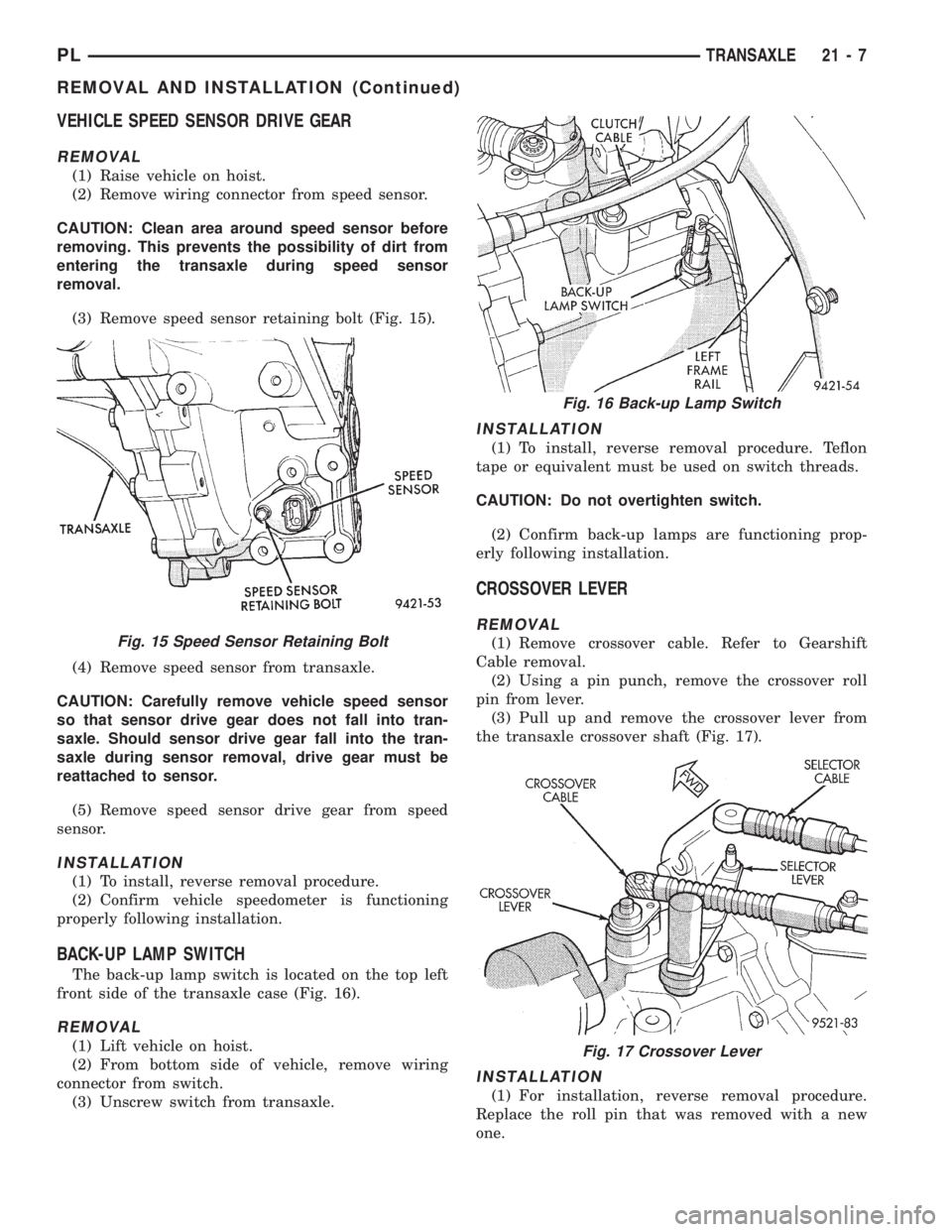
(3) Remove speed sensor retaining bolt (Fig. 15).
(4) Remove speed sensor from transaxle.
CAUTION: Carefully remove vehicle speed sensor
so that sensor drive gear does not fall into tran-
saxle. Should sensor drive gear fall into the tran-
saxle during sensor removal, drive gear must be
reattached to sensor.
(5) Remove speed sensor drive gear from speed
sensor.
INSTALLATION
(1) To install, reverse removal procedure.
(2) Confirm vehicle speedometer is functioning
properly following installation.
BACK-UP LAMP SWITCH
The back-up lamp switch is located on the top left
front side of the transaxle case (Fig. 16).
REMOVAL
(1) Lift vehicle on hoist.
(2) From bottom side of vehicle, remove wiring
connector from switch.
(3) Unscrew switch from transaxle.
INSTALLATION
(1) To install, reverse removal procedure. Teflon
tape or equivalent must be used on switch threads.
CAUTION: Do not overtighten switch.
(2) Confirm back-up lamps are functioning prop-
erly following installation.
CROSSOVER LEVER
REMOVAL
(1) Remove crossover cable. Refer to Gearshift
Cable removal.
(2) Using a pin punch, remove the crossover roll
pin from lever.
(3) Pull up and remove the crossover lever from
the transaxle crossover shaft (Fig. 17).
INSTALLATION
(1) For installation, reverse removal procedure.
Replace the roll pin that was removed with a new
one.
Fig. 15 Speed Sensor Retaining Bolt
Fig. 16 Back-up Lamp Switch
Fig. 17 Crossover Lever
PLTRANSAXLE 21 - 7
REMOVAL AND INSTALLATION (Continued)