DODGE NEON 1999 Service Repair Manual
Manufacturer: DODGE, Model Year: 1999, Model line: NEON, Model: DODGE NEON 1999Pages: 1200, PDF Size: 35.29 MB
Page 971 of 1200
INSTALLATION
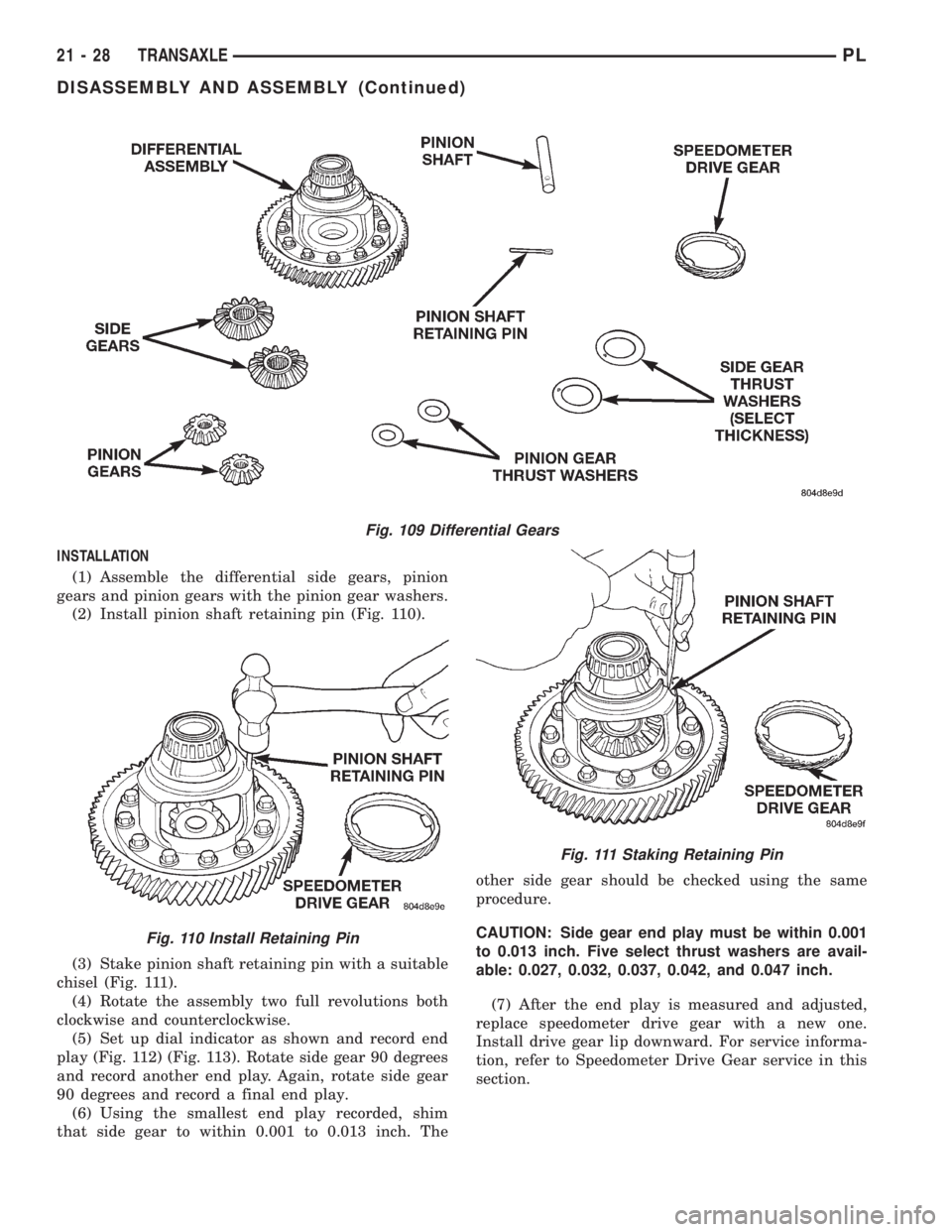
(1) Assemble the differential side gears, pinion
gears and pinion gears with the pinion gear washers.
(2) Install pinion shaft retaining pin (Fig. 110).
(3) Stake pinion shaft retaining pin with a suitable
chisel (Fig. 111).
(4) Rotate the assembly two full revolutions both
clockwise and counterclockwise.
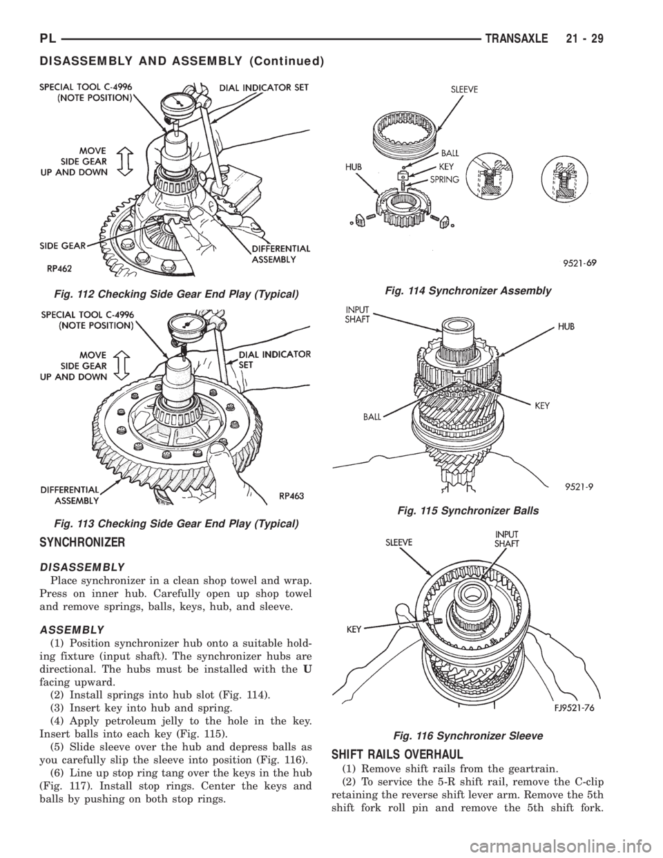
(5) Set up dial indicator as shown and record end
play (Fig. 112) (Fig. 113). Rotate side gear 90 degrees
and record another end play. Again, rotate side gear
90 degrees and record a final end play.
(6) Using the smallest end play recorded, shim
that side gear to within 0.001 to 0.013 inch. Theother side gear should be checked using the same
procedure.
CAUTION: Side gear end play must be within 0.001
to 0.013 inch. Five select thrust washers are avail-
able: 0.027, 0.032, 0.037, 0.042, and 0.047 inch.
(7) After the end play is measured and adjusted,
replace speedometer drive gear with a new one.
Install drive gear lip downward. For service informa-
tion, refer to Speedometer Drive Gear service in this
section.
Fig. 109 Differential Gears
Fig. 110 Install Retaining Pin
Fig. 111 Staking Retaining Pin
21 - 28 TRANSAXLEPL
DISASSEMBLY AND ASSEMBLY (Continued)
Page 972 of 1200
SYNCHRONIZER
DISASSEMBLY
Place synchronizer in a clean shop towel and wrap.
Press on inner hub. Carefully open up shop towel
and remove springs, balls, keys, hub, and sleeve.
ASSEMBLY
(1) Position synchronizer hub onto a suitable hold-
ing fixture (input shaft). The synchronizer hubs are
directional. The hubs must be installed with theU
facing upward.
(2) Install springs into hub slot (Fig. 114).
(3) Insert key into hub and spring.
(4) Apply petroleum jelly to the hole in the key.
Insert balls into each key (Fig. 115).
(5) Slide sleeve over the hub and depress balls as
you carefully slip the sleeve into position (Fig. 116).
(6) Line up stop ring tang over the keys in the hub
(Fig. 117). Install stop rings. Center the keys and
balls by pushing on both stop rings.
SHIFT RAILS OVERHAUL
(1) Remove shift rails from the geartrain.
(2) To service the 5-R shift rail, remove the C-clip
retaining the reverse shift lever arm. Remove the 5th
shift fork roll pin and remove the 5th shift fork.
Fig. 112 Checking Side Gear End Play (Typical)
Fig. 113 Checking Side Gear End Play (Typical)
Fig. 114 Synchronizer Assembly
Fig. 115 Synchronizer Balls
Fig. 116 Synchronizer Sleeve
PLTRANSAXLE 21 - 29
DISASSEMBLY AND ASSEMBLY (Continued)
Page 973 of 1200
Remove the shift lug roll pin and remove the shift
lug. Replace parts as necessary.
(3) To service the 3-4 shift rail, remove the roll pin
retaining the 3-4 shift fork. Remove the shift fork.
Remove the shift lug roll pin and remove the shift
lug. Replace parts as necessary.
(4) To service the 1-2 shift rail, remove the roll pin
retaining the 1-2 shift fork. Remove the shift fork
and replace parts as necessary.
TRANSAXLE CASE OVERHAUL
The sealant used to seal the transaxle case halves
is MopartGasket Maker, Loctitet518, or equivalent.
The sealant used for the bearing end±plate cover is
MopartRTV.
The components that are left in the gear cases
when the gear train is pulled out are the:
²Axle shaft seals
²Output bearing race and retainer
²Input bearing and sleeve
²Differential bearing cones
²Shift rail bushings
²Shift shafts
²Shift shaft seals
²Shift shaft bushings
²Rear bearing oil feed trough
AXLE SHAFT SEALS
REMOVAL
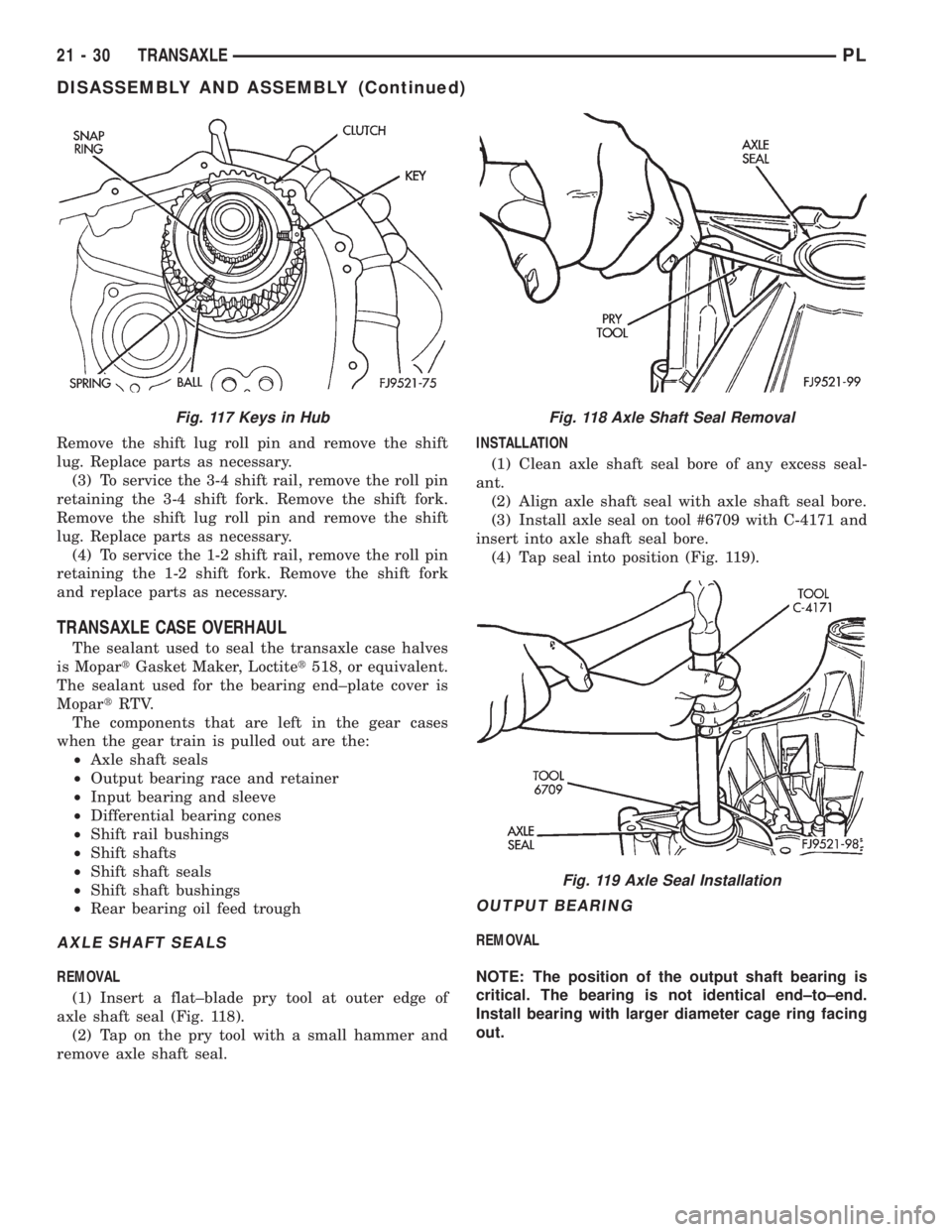
(1) Insert a flat±blade pry tool at outer edge of
axle shaft seal (Fig. 118).
(2) Tap on the pry tool with a small hammer and
remove axle shaft seal.INSTALLATION
(1) Clean axle shaft seal bore of any excess seal-
ant.
(2) Align axle shaft seal with axle shaft seal bore.
(3) Install axle seal on tool #6709 with C-4171 and
insert into axle shaft seal bore.
(4) Tap seal into position (Fig. 119).
OUTPUT BEARING
REMOVAL
NOTE: The position of the output shaft bearing is
critical. The bearing is not identical end±to±end.
Install bearing with larger diameter cage ring facing
out.
Fig. 117 Keys in HubFig. 118 Axle Shaft Seal Removal
Fig. 119 Axle Seal Installation
21 - 30 TRANSAXLEPL
DISASSEMBLY AND ASSEMBLY (Continued)
Page 974 of 1200
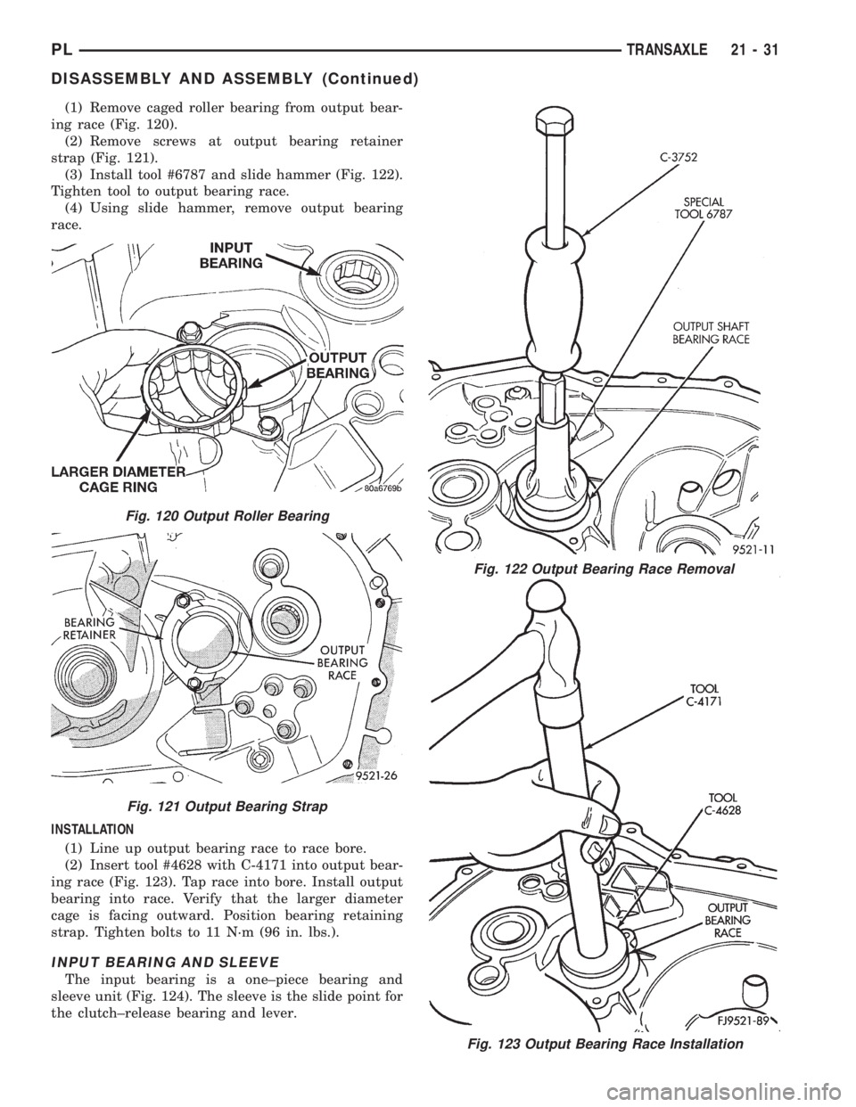
(1) Remove caged roller bearing from output bear-
ing race (Fig. 120).
(2) Remove screws at output bearing retainer
strap (Fig. 121).
(3) Install tool #6787 and slide hammer (Fig. 122).
Tighten tool to output bearing race.
(4) Using slide hammer, remove output bearing
race.
INSTALLATION
(1) Line up output bearing race to race bore.
(2) Insert tool #4628 with C-4171 into output bear-
ing race (Fig. 123). Tap race into bore. Install output
bearing into race. Verify that the larger diameter
cage is facing outward. Position bearing retaining
strap. Tighten bolts to 11 N´m (96 in. lbs.).
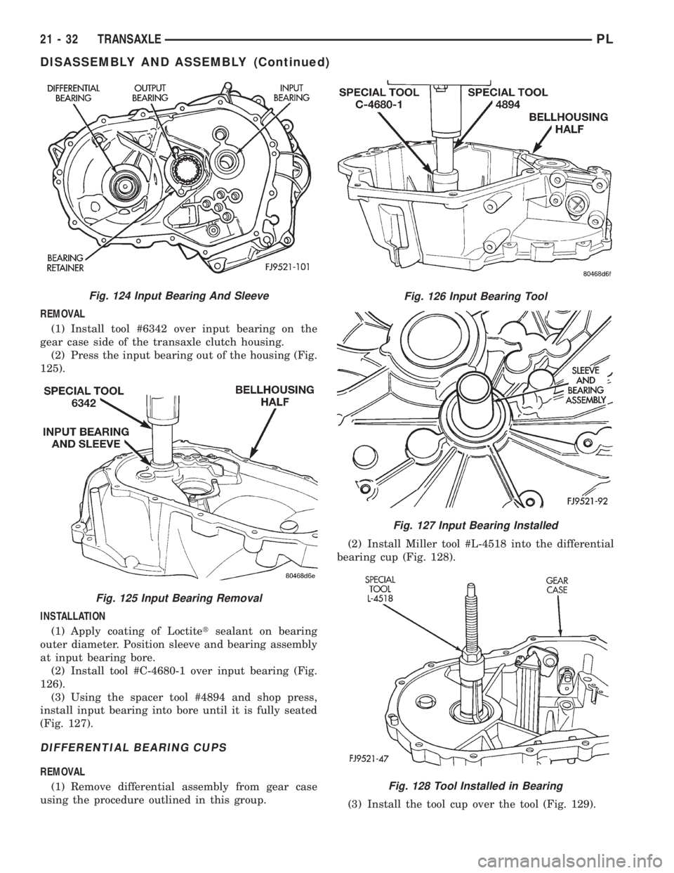
INPUT BEARING AND SLEEVE
The input bearing is a one±piece bearing and
sleeve unit (Fig. 124). The sleeve is the slide point for
the clutch±release bearing and lever.
Fig. 123 Output Bearing Race Installation
Fig. 120 Output Roller Bearing
Fig. 121 Output Bearing Strap
Fig. 122 Output Bearing Race Removal
PLTRANSAXLE 21 - 31
DISASSEMBLY AND ASSEMBLY (Continued)
Page 975 of 1200
REMOVAL
(1) Install tool #6342 over input bearing on the
gear case side of the transaxle clutch housing.
(2) Press the input bearing out of the housing (Fig.
125).
INSTALLATION
(1) Apply coating of Loctitetsealant on bearing
outer diameter. Position sleeve and bearing assembly
at input bearing bore.
(2) Install tool #C-4680-1 over input bearing (Fig.
126).
(3) Using the spacer tool #4894 and shop press,
install input bearing into bore until it is fully seated
(Fig. 127).
DIFFERENTIAL BEARING CUPS
REMOVAL
(1) Remove differential assembly from gear case
using the procedure outlined in this group.(2) Install Miller tool #L-4518 into the differential
bearing cup (Fig. 128).
(3) Install the tool cup over the tool (Fig. 129).
Fig. 124 Input Bearing And Sleeve
Fig. 125 Input Bearing Removal
Fig. 126 Input Bearing Tool
Fig. 127 Input Bearing Installed
Fig. 128 Tool Installed in Bearing
21 - 32 TRANSAXLEPL
DISASSEMBLY AND ASSEMBLY (Continued)
Page 976 of 1200
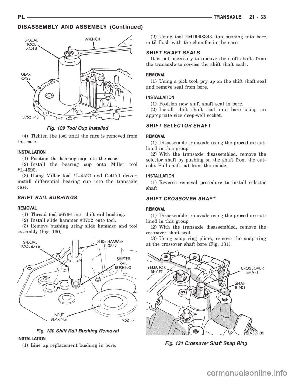
(4) Tighten the tool until the race is removed from
the case.
INSTALLATION
(1) Position the bearing cup into the case.
(2) Install the bearing cup onto Miller tool
#L-4520.
(3) Using Miller tool #L-4520 and C-4171 driver,
install differential bearing cup into the transaxle
case.
SHIFT RAIL BUSHINGS
REMOVAL
(1) Thread tool #6786 into shift rail bushing.
(2) Install slide hammer #3752 onto tool.
(3) Remove bushing using slide hammer and tool
assembly (Fig. 130).
INSTALLATION
(1) Line up replacement bushing in bore.(2) Using tool #MD998343, tap bushing into bore
until flush with the chamfer in the case.
SHIFT SHAFT SEALS
It is not necessary to remove the shift shafts from
the transaxle to service the shift shaft seals.
REMOVAL
(1) Using a pick tool, pry up on the shift shaft seal
and remove seal from bore.
INSTALLATION
(1) Position new shift shaft seal in bore.
(2) Install shift shaft seal into bore using an
appropriate size deep-well socket.
SHIFT SELECTOR SHAFT
REMOVAL
(1) Disassemble transaxle using the procedure out-
lined in this group.
(2) With the transaxle disassembled, remove the
selector shaft by pushing on the shaft from the out-
side. Pull shaft out from the inside.
INSTALLATION
(1) Reverse removal procedure to install selector
shaft.
SHIFT CROSSOVER SHAFT
REMOVAL
(1) Disassemble transaxle using the procedure out-
lined in this group.
(2) With the transaxle disassembled, remove the
crossover shaft seal.
(3) Using snap±ring pliers, remove the snap ring
at the crossover shaft bore (Fig. 131).
Fig. 129 Tool Cup Installed
Fig. 130 Shift Rail Bushing Removal
Fig. 131 Crossover Shaft Snap Ring
PLTRANSAXLE 21 - 33
DISASSEMBLY AND ASSEMBLY (Continued)
Page 977 of 1200
(4) Push the crossover shaft in the case and
remove the crossover assembly.
INSTALLATION
(1) Reverse removal procedure to install crossover
shaft.
SHIFT SELECTOR SHAFT BUSHING
REMOVAL
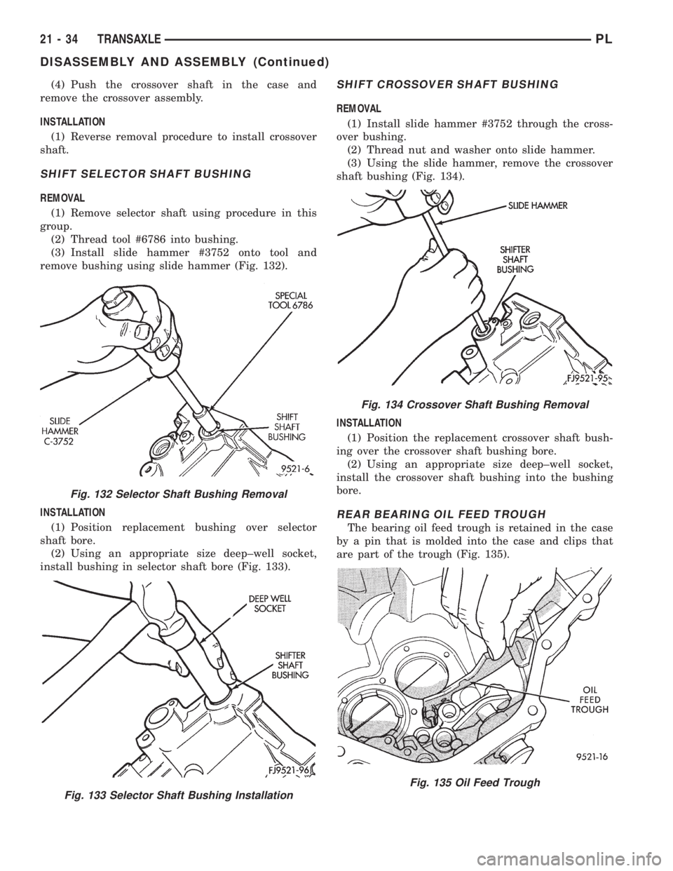
(1) Remove selector shaft using procedure in this
group.
(2) Thread tool #6786 into bushing.
(3) Install slide hammer #3752 onto tool and
remove bushing using slide hammer (Fig. 132).
INSTALLATION
(1) Position replacement bushing over selector
shaft bore.
(2) Using an appropriate size deep±well socket,
install bushing in selector shaft bore (Fig. 133).
SHIFT CROSSOVER SHAFT BUSHING
REMOVAL
(1) Install slide hammer #3752 through the cross-
over bushing.
(2) Thread nut and washer onto slide hammer.
(3) Using the slide hammer, remove the crossover
shaft bushing (Fig. 134).
INSTALLATION
(1) Position the replacement crossover shaft bush-
ing over the crossover shaft bushing bore.
(2) Using an appropriate size deep±well socket,
install the crossover shaft bushing into the bushing
bore.
REAR BEARING OIL FEED TROUGH
The bearing oil feed trough is retained in the case
by a pin that is molded into the case and clips that
are part of the trough (Fig. 135).
Fig. 132 Selector Shaft Bushing Removal
Fig. 133 Selector Shaft Bushing Installation
Fig. 134 Crossover Shaft Bushing Removal
Fig. 135 Oil Feed Trough
21 - 34 TRANSAXLEPL
DISASSEMBLY AND ASSEMBLY (Continued)
Page 978 of 1200
REMOVAL
(1) Using light plier pressure, squeeze the clips
together at the rear of the trough.
(2) Slide the trough over the retaining pin that
locates the trough in the case.
INSTALLATION
(1) Reverse removal procedure to install oil feed
trough.
CLEANING AND INSPECTION
TRANSAXLE
Clean the gears, bearings, shafts, synchronizers,
thrust washers, oil feeder, shift mechanism, gear
case, and bellhousing with solvent. Dry all parts
except the bearings with compressed air. Allow the
bearings to either air dry or wipe them dry with
clean shop towels.
Inspect the gears, bearings, shafts and thrust
washers. Replace the bearings and cups if the rollers
are worn, chipped, cracked, flat spotted, or brin-
nelled, or if the bearing cage is damaged or distorted.
Replace the thrust washers if cracked, chipped, or
worn. Replace the gears if the teeth are chipped,
cracked, or worn thin. Inspect the synchronizers.
Replace the sleeve if worn or damaged in any way.
Replace the stop rings if the friction material is
burned, flaking off, or worn. Check the condition of
the synchro keys and springs. Replace these parts if
worn, cracked, or distorted.
SYNCHRONIZER
CLEAN
Do not attempt to clean the blocking rings in sol-
vent. The friction material will become contaminated.
Place synchronizer components in a suitable holder
and clean with solvent. Air dry.
INSPECT
Proper inspection of components involve:
²Teeth, for wear, scuffed, nicked, burred, or bro-
ken teeth
²Keys, for wear or distortion
²Balls and springs, for distortion, cracks, or wear
If any of these conditions exist in these compo-
nents, replace as necessary.
ADJUSTMENTS
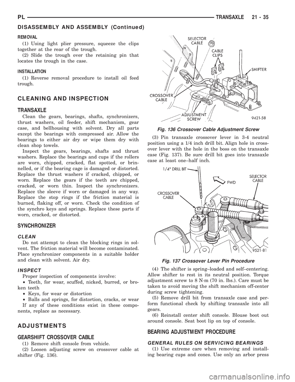
GEARSHIFT CROSSOVER CABLE
(1) Remove shift console from vehicle.
(2) Loosen adjusting screw on crossover cable at
shifter (Fig. 136).(3) Pin transaxle crossover lever in 3-4 neutral
position using a 1/4 inch drill bit. Align hole in cross-
over lever with the hole in the boss on the transaxle
case (Fig. 137). Be sure drill bit goes into transaxle
case at least one±half inch.
(4) The shifter is spring±loaded and self±centering.
Allow shifter to rest in its neutral position. Torque
adjustment screw to 8 N´m (70 in. lbs.). Care must be
taken to avoid moving the shift mechanism off-center
during screw tightening.
(5) Remove drill bit from transaxle case and per-
form functional check by shifting transaxle into all
gears.
(6) Reinstall center shift console. Blouse boot out
around console. Seat boot lip on top of console.
BEARING ADJUSTMENT PROCEDURE
GENERAL RULES ON SERVICING BEARINGS
(1) Use extreme care when removing and install-
ing bearing cups and cones. Use only an arbor press
Fig. 136 Crossover Cable Adjustment Screw
Fig. 137 Crossover Lever Pin Procedure
PLTRANSAXLE 21 - 35
DISASSEMBLY AND ASSEMBLY (Continued)
Page 979 of 1200
for installation, as a hammer may not properly align
the bearing cup or cone. Burrs or nicks on the bear-
ing seat will give a false end play reading while
gauging for proper shims. Improperly seated bearing
cups and cones are subject to low±mileage failure.
(2) Bearing cups and cones should be replaced if
they show signs of pitting or heat distress. If distress
is seen on either the cup or bearing rollers, both cup
and cone must be replaced.
(3) Bearing preload and drag torque specifications
must be maintained to avoid premature bearing fail-
ures. Used (original) bearings may lose up to 50% of
their original drag torque after break in. All bearing
adjustments must be made with no other component
interference or gear intermesh.
(4) Replace bearings as a pair: If one differential
bearing is defective, replace both differential bear-
ings, if one input shaft bearing is defective, replace
both input shaft bearings.
(5) Bearing cones must not be reused if removed.
(6) Turning torque readings should be obtained
while smoothly rotating in either direction.
DIFFERENTIAL BEARING PRELOAD ADJUSTMENT
NOTE: True bearing turning torque readings can be
obtained only with the geartrain removed from the
case.
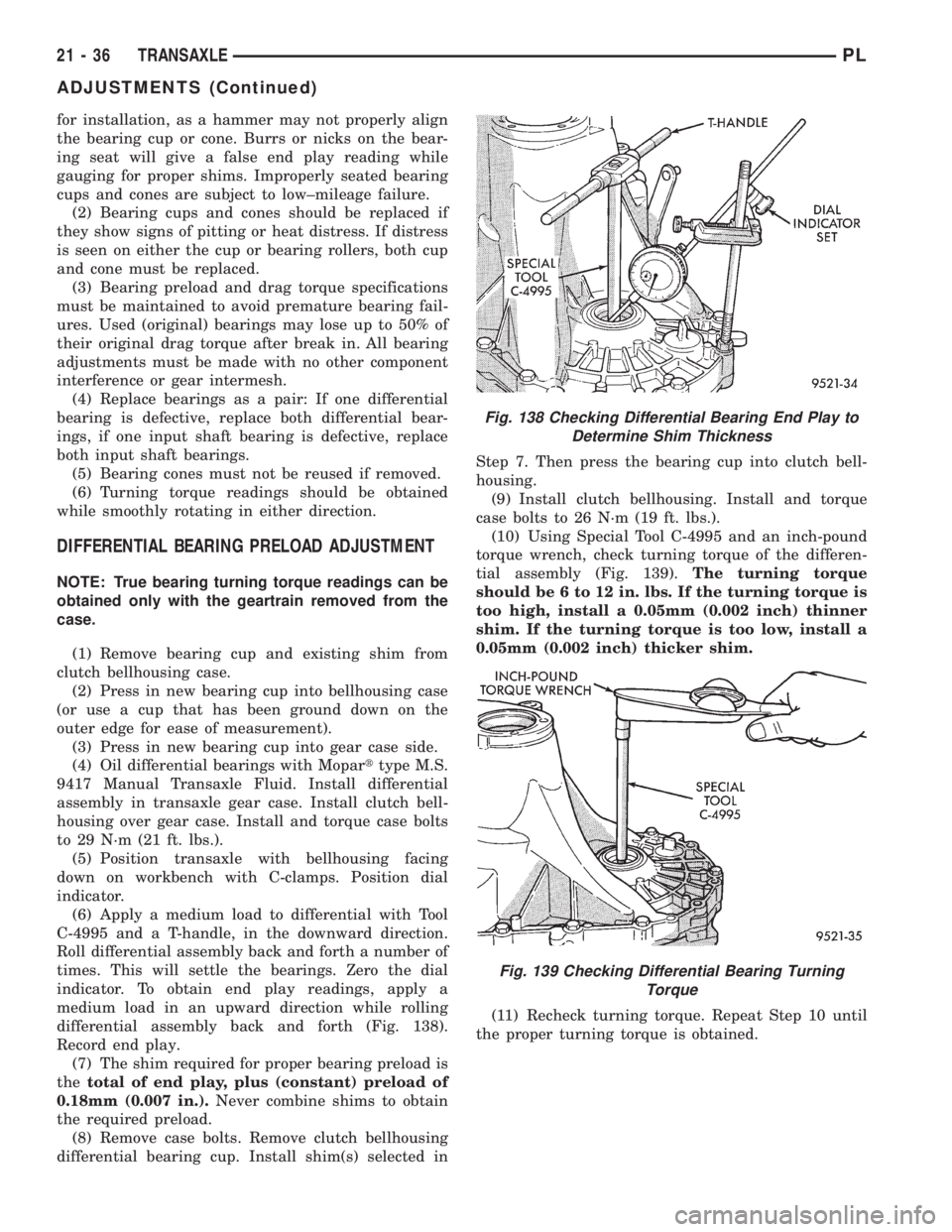
(1) Remove bearing cup and existing shim from
clutch bellhousing case.
(2) Press in new bearing cup into bellhousing case
(or use a cup that has been ground down on the
outer edge for ease of measurement).
(3) Press in new bearing cup into gear case side.
(4) Oil differential bearings with Moparttype M.S.
9417 Manual Transaxle Fluid. Install differential
assembly in transaxle gear case. Install clutch bell-
housing over gear case. Install and torque case bolts
to 29 N´m (21 ft. lbs.).
(5) Position transaxle with bellhousing facing
down on workbench with C-clamps. Position dial
indicator.
(6) Apply a medium load to differential with Tool
C-4995 and a T-handle, in the downward direction.
Roll differential assembly back and forth a number of
times. This will settle the bearings. Zero the dial
indicator. To obtain end play readings, apply a
medium load in an upward direction while rolling
differential assembly back and forth (Fig. 138).
Record end play.
(7) The shim required for proper bearing preload is
thetotal of end play, plus (constant) preload of
0.18mm (0.007 in.).Never combine shims to obtain
the required preload.
(8) Remove case bolts. Remove clutch bellhousing
differential bearing cup. Install shim(s) selected inStep 7. Then press the bearing cup into clutch bell-
housing.
(9) Install clutch bellhousing. Install and torque
case bolts to 26 N´m (19 ft. lbs.).
(10) Using Special Tool C-4995 and an inch-pound
torque wrench, check turning torque of the differen-
tial assembly (Fig. 139).The turning torque
should be 6 to 12 in. lbs. If the turning torque is
too high, install a 0.05mm (0.002 inch) thinner
shim. If the turning torque is too low, install a
0.05mm (0.002 inch) thicker shim.
(11) Recheck turning torque. Repeat Step 10 until
the proper turning torque is obtained.
Fig. 138 Checking Differential Bearing End Play to
Determine Shim Thickness
Fig. 139 Checking Differential Bearing Turning
Torque
21 - 36 TRANSAXLEPL
ADJUSTMENTS (Continued)
Page 980 of 1200
SPECIFICATIONS
NV T350 (A-578)
DESCRIPTION TORQUE
Back-up Lamp Switch..........24N´m(18ft.lbs.)
Crossover Cable Adj. Screw......8N´m(70in.lbs.)
Drain Plug.................30N´m(267 in. lbs.)
Differential Ring Gear Bolts.....81N´m(60ft.lbs.)
Dust Shield to Transaxle......12N´m(105 in. lbs.)
End Plate Cover Bolts.........29N´m(21ft.lbs.)
Front Engine Mount to Trans . . .108 N´m (80 ft. lbs.)
Front Mount Through Bolt......61N´m(45ft.lbs.)
Front Mount to Engine Bolt.....54N´m(40ft.lbs.)
Lateral Bending
Strut to Engine.............54N´m(40ft.lbs.)
Lateral Bending Strut to Trans. . .54 N´m (40 ft. lbs.)
Left Mount Through Bolt......108 N´m (80 ft. lbs.)
Left Mount to Transaxle........54N´m(40ft.lbs.)
Output Bearing Race Ret. Strap .11 N´m (96 in. lbs.)
Power Hop Damper Bkt. to
Trans.....................54N´m(40ft.lbs.)
Power Hop Damper to
Frame Bkt.................54N´m(40ft.lbs.)
Power Hop Damper to
Trans. Bkt.................54N´m(40ft.lbs.)
Reverse Fork Bracket..........11N´m(96in.lbs.)
Reverse Idler Shaft Bolt........26N´m(19ft.lbs.)
Shift Cable Bracket to
Transaxle................28N´m(250 in. lbs.)
Transaxle Case Bolts..........29N´m(21ft.lbs.)
Transaxle to Engine Bolt.......95N´m(70ft.lbs.)
Trans. to Eng. Intake Bkt. Bolts . .95 N´m (70 ft. lbs.)
Vehicle Speed Sensor...........7N´m(60in.lbs.)
Vertical Bending Strut to
Engine..................108 N´m (80 ft. lbs.)
Vertical Bending Strut to Trans. .108 N´m (80 ft. lbs.)
NOTE: Bolts that have thread sealer or torque lock
patches should not be reused. Always install new
bolts in these applications.
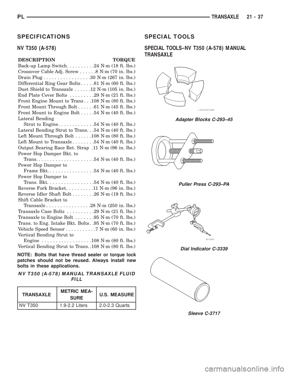
SPECIAL TOOLS
SPECIAL TOOLS±NV T350 (A-578) MANUAL
TRANSAXLE
NV T350 (A-578) MANUAL TRANSAXLE FLUID
FILL
TRANSAXLEMETRIC MEA-
SUREU.S. MEASURE
NV T350 1.9-2.2 Liters 2.0-2.3 Quarts
Adapter Blocks C-293±45
Puller Press C-293±PA
Dial Indicator C-3339
Sleeve C-3717
PLTRANSAXLE 21 - 37