DODGE NEON 1999 Service Repair Manual
Manufacturer: DODGE, Model Year: 1999, Model line: NEON, Model: DODGE NEON 1999Pages: 1200, PDF Size: 35.29 MB
Page 961 of 1200
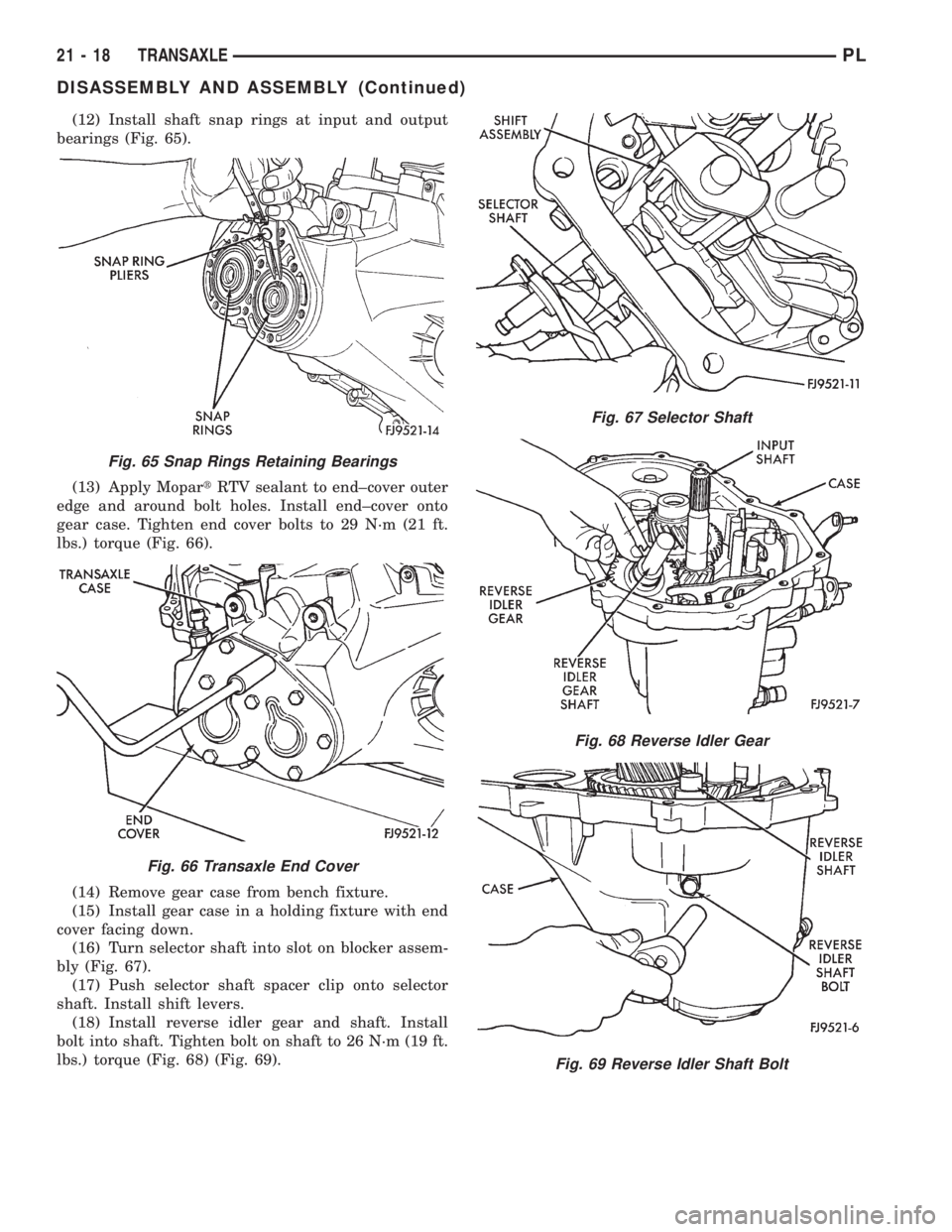
(12) Install shaft snap rings at input and output
bearings (Fig. 65).
(13) Apply MopartRTV sealant to end±cover outer
edge and around bolt holes. Install end±cover onto
gear case. Tighten end cover bolts to 29 N´m (21 ft.
lbs.) torque (Fig. 66).
(14) Remove gear case from bench fixture.
(15) Install gear case in a holding fixture with end
cover facing down.
(16) Turn selector shaft into slot on blocker assem-
bly (Fig. 67).
(17) Push selector shaft spacer clip onto selector
shaft. Install shift levers.
(18) Install reverse idler gear and shaft. Install
bolt into shaft. Tighten bolt on shaft to 26 N´m (19 ft.
lbs.) torque (Fig. 68) (Fig. 69).
Fig. 65 Snap Rings Retaining Bearings
Fig. 66 Transaxle End Cover
Fig. 67 Selector Shaft
Fig. 68 Reverse Idler Gear
Fig. 69 Reverse Idler Shaft Bolt
21 - 18 TRANSAXLEPL
DISASSEMBLY AND ASSEMBLY (Continued)
Page 962 of 1200
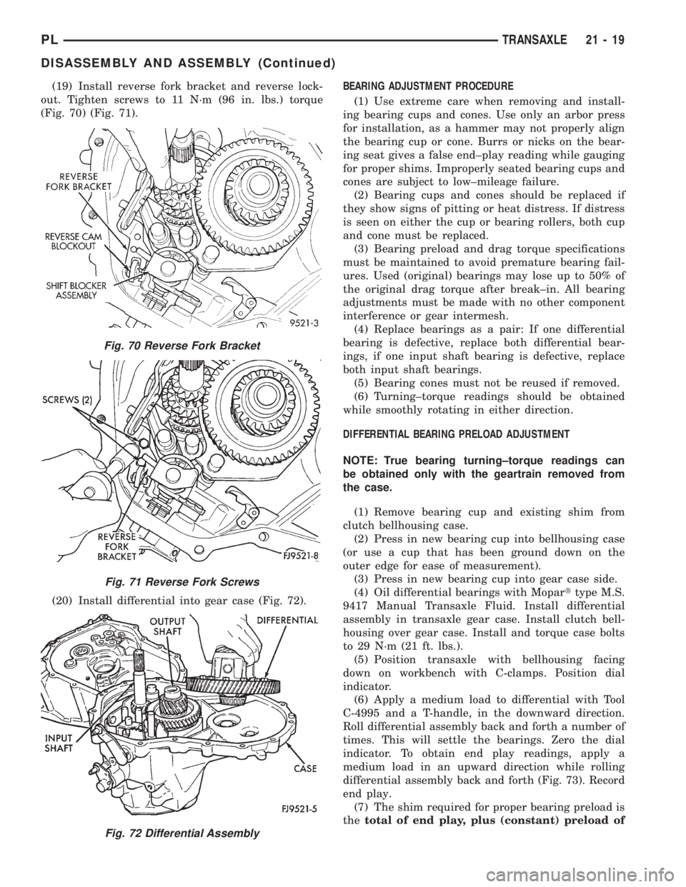
(19) Install reverse fork bracket and reverse lock-
out. Tighten screws to 11 N´m (96 in. lbs.) torque
(Fig. 70) (Fig. 71).
(20) Install differential into gear case (Fig. 72).BEARING ADJUSTMENT PROCEDURE
(1) Use extreme care when removing and install-
ing bearing cups and cones. Use only an arbor press
for installation, as a hammer may not properly align
the bearing cup or cone. Burrs or nicks on the bear-
ing seat gives a false end±play reading while gauging
for proper shims. Improperly seated bearing cups and
cones are subject to low±mileage failure.
(2) Bearing cups and cones should be replaced if
they show signs of pitting or heat distress. If distress
is seen on either the cup or bearing rollers, both cup
and cone must be replaced.
(3) Bearing preload and drag torque specifications
must be maintained to avoid premature bearing fail-
ures. Used (original) bearings may lose up to 50% of
the original drag torque after break±in. All bearing
adjustments must be made with no other component
interference or gear intermesh.
(4) Replace bearings as a pair: If one differential
bearing is defective, replace both differential bear-
ings, if one input shaft bearing is defective, replace
both input shaft bearings.
(5) Bearing cones must not be reused if removed.
(6) Turning±torque readings should be obtained
while smoothly rotating in either direction.
DIFFERENTIAL BEARING PRELOAD ADJUSTMENT
NOTE: True bearing turning±torque readings can
be obtained only with the geartrain removed from
the case.
(1) Remove bearing cup and existing shim from
clutch bellhousing case.
(2) Press in new bearing cup into bellhousing case
(or use a cup that has been ground down on the
outer edge for ease of measurement).
(3) Press in new bearing cup into gear case side.
(4) Oil differential bearings with Moparttype M.S.
9417 Manual Transaxle Fluid. Install differential
assembly in transaxle gear case. Install clutch bell-
housing over gear case. Install and torque case bolts
to 29 N´m (21 ft. lbs.).
(5) Position transaxle with bellhousing facing
down on workbench with C-clamps. Position dial
indicator.
(6) Apply a medium load to differential with Tool
C-4995 and a T-handle, in the downward direction.
Roll differential assembly back and forth a number of
times. This will settle the bearings. Zero the dial
indicator. To obtain end play readings, apply a
medium load in an upward direction while rolling
differential assembly back and forth (Fig. 73). Record
end play.
(7) The shim required for proper bearing preload is
thetotal of end play, plus (constant) preload of
Fig. 70 Reverse Fork Bracket
Fig. 71 Reverse Fork Screws
Fig. 72 Differential Assembly
PLTRANSAXLE 21 - 19
DISASSEMBLY AND ASSEMBLY (Continued)
Page 963 of 1200
0.18mm (0.007 in.).Never combine shims to obtain
the required preload.
(8) Remove case bolts. Remove clutch bellhousing
differential bearing cup. Install shim(s) selected in
Step 7. Then press the bearing cup into clutch bell-
housing.
(9) Install clutch bellhousing. Install and torque
case bolts to 26 N´m (19 ft. lbs.).
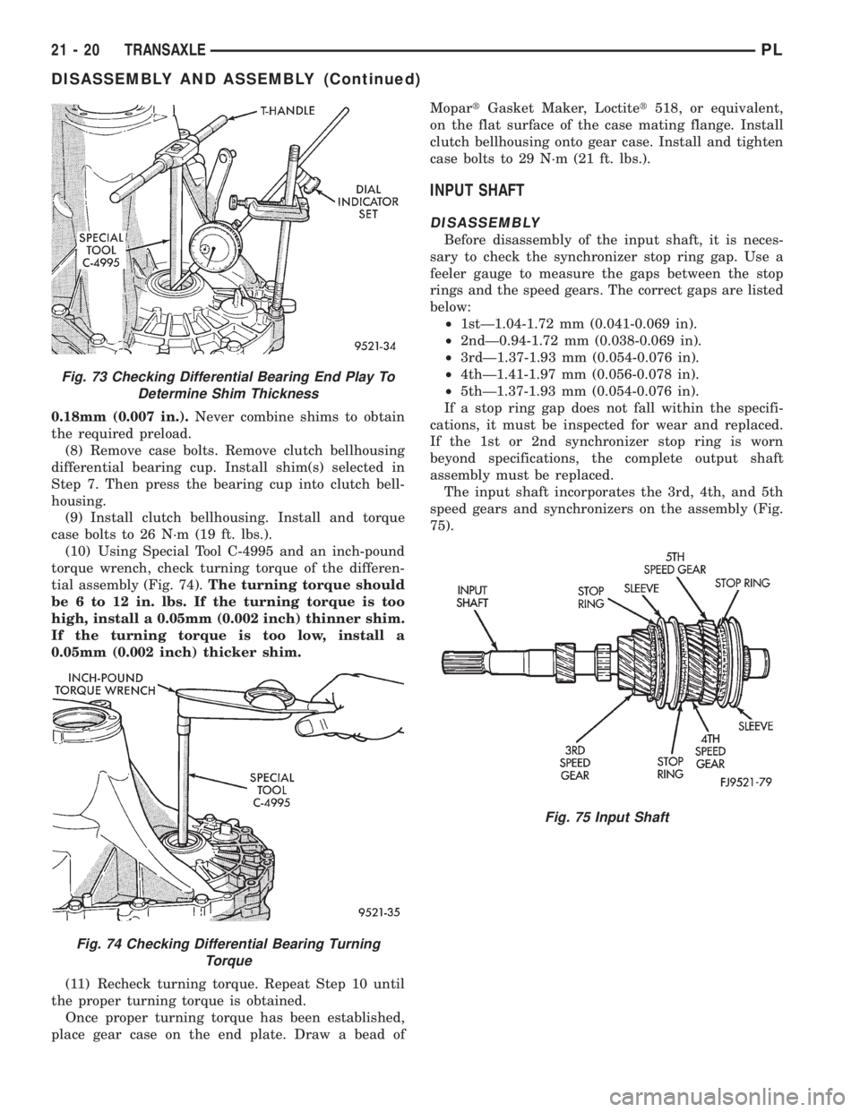
(10) Using Special Tool C-4995 and an inch-pound
torque wrench, check turning torque of the differen-
tial assembly (Fig. 74).The turning torque should
be 6 to 12 in. lbs. If the turning torque is too
high, install a 0.05mm (0.002 inch) thinner shim.
If the turning torque is too low, install a
0.05mm (0.002 inch) thicker shim.
(11) Recheck turning torque. Repeat Step 10 until
the proper turning torque is obtained.
Once proper turning torque has been established,
place gear case on the end plate. Draw a bead ofMopartGasket Maker, Loctitet518, or equivalent,
on the flat surface of the case mating flange. Install
clutch bellhousing onto gear case. Install and tighten
case bolts to 29 N´m (21 ft. lbs.).
INPUT SHAFT
DISASSEMBLY
Before disassembly of the input shaft, it is neces-
sary to check the synchronizer stop ring gap. Use a
feeler gauge to measure the gaps between the stop
rings and the speed gears. The correct gaps are listed
below:
²1stÐ1.04-1.72 mm (0.041-0.069 in).
²2ndÐ0.94-1.72 mm (0.038-0.069 in).
²3rdÐ1.37-1.93 mm (0.054-0.076 in).
²4thÐ1.41-1.97 mm (0.056-0.078 in).
²5thÐ1.37-1.93 mm (0.054-0.076 in).
If a stop ring gap does not fall within the specifi-
cations, it must be inspected for wear and replaced.
If the 1st or 2nd synchronizer stop ring is worn
beyond specifications, the complete output shaft
assembly must be replaced.
The input shaft incorporates the 3rd, 4th, and 5th
speed gears and synchronizers on the assembly (Fig.
75).
Fig. 73 Checking Differential Bearing End Play To
Determine Shim Thickness
Fig. 74 Checking Differential Bearing Turning
Torque
Fig. 75 Input Shaft
21 - 20 TRANSAXLEPL
DISASSEMBLY AND ASSEMBLY (Continued)
Page 964 of 1200
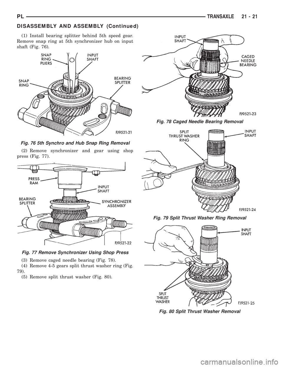
(1) Install bearing splitter behind 5th speed gear.
Remove snap ring at 5th synchronizer hub on input
shaft (Fig. 76).
(2) Remove synchronizer and gear using shop
press (Fig. 77).
(3) Remove caged needle bearing (Fig. 78).
(4) Remove 4-5 gears split thrust washer ring (Fig.
79).
(5) Remove split thrust washer (Fig. 80).
Fig. 76 5th Synchro and Hub Snap Ring Removal
Fig. 77 Remove Synchronizer Using Shop Press
Fig. 78 Caged Needle Bearing Removal
Fig. 79 Split Thrust Washer Ring Removal
Fig. 80 Split Thrust Washer Removal
PLTRANSAXLE 21 - 21
DISASSEMBLY AND ASSEMBLY (Continued)
Page 965 of 1200
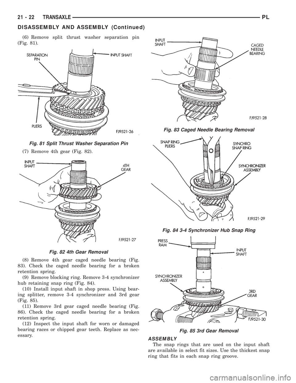
(6) Remove split thrust washer separation pin
(Fig. 81).
(7) Remove 4th gear (Fig. 82).
(8) Remove 4th gear caged needle bearing (Fig.
83). Check the caged needle bearing for a broken
retention spring.
(9) Remove blocking ring. Remove 3-4 synchronizer
hub retaining snap ring (Fig. 84).
(10) Install input shaft in shop press. Using bear-
ing splitter, remove 3-4 synchronizer and 3rd gear
(Fig. 85).
(11) Remove 3rd gear caged needle bearing (Fig.
86). Check the caged needle bearing for a broken
retention spring.
(12) Inspect the input shaft for worn or damaged
bearing races or chipped gear teeth. Replace as nec-
essary.
ASSEMBLY
The snap rings that are used on the input shaft
are available in select fit sizes. Use the thickest snap
ring that fits in each snap ring groove.
Fig. 81 Split Thrust Washer Separation Pin
Fig. 82 4th Gear Removal
Fig. 83 Caged Needle Bearing Removal
Fig. 84 3-4 Synchronizer Hub Snap Ring
Fig. 85 3rd Gear Removal
21 - 22 TRANSAXLEPL
DISASSEMBLY AND ASSEMBLY (Continued)
Page 966 of 1200
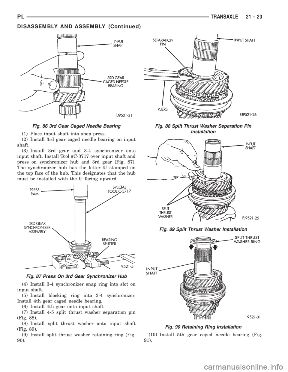
(1) Place input shaft into shop press.
(2) Install 3rd gear caged needle bearing on input
shaft.
(3) Install 3rd gear and 3-4 synchronizer onto
input shaft. Install Tool #C-3717 over input shaft and
press on synchronizer hub and 3rd gear (Fig. 87).
The synchronizer hub has the letterUstamped on
the top face of the hub. This designates that the hub
must be installed with theUfacing upward.
(4) Install 3-4 synchronizer snap ring into slot on
input shaft.
(5) Install blocking ring into 3-4 synchronizer.
Install 4th gear caged needle bearing.
(6) Install 4th gear onto input shaft.
(7) Install 4-5 split thrust washer separation pin
(Fig. 88).
(8) Install split thrust washer onto input shaft
(Fig. 89).
(9) Install split thrust washer retaining ring (Fig.
90).(10) Install 5th gear caged needle bearing (Fig.
91).
Fig. 86 3rd Gear Caged Needle Bearing
Fig. 87 Press On 3rd Gear Synchronizer Hub
Fig. 88 Split Thrust Washer Separation Pin
Installation
Fig. 89 Split Thrust Washer Installation
Fig. 90 Retaining Ring Installation
PLTRANSAXLE 21 - 23
DISASSEMBLY AND ASSEMBLY (Continued)
Page 967 of 1200
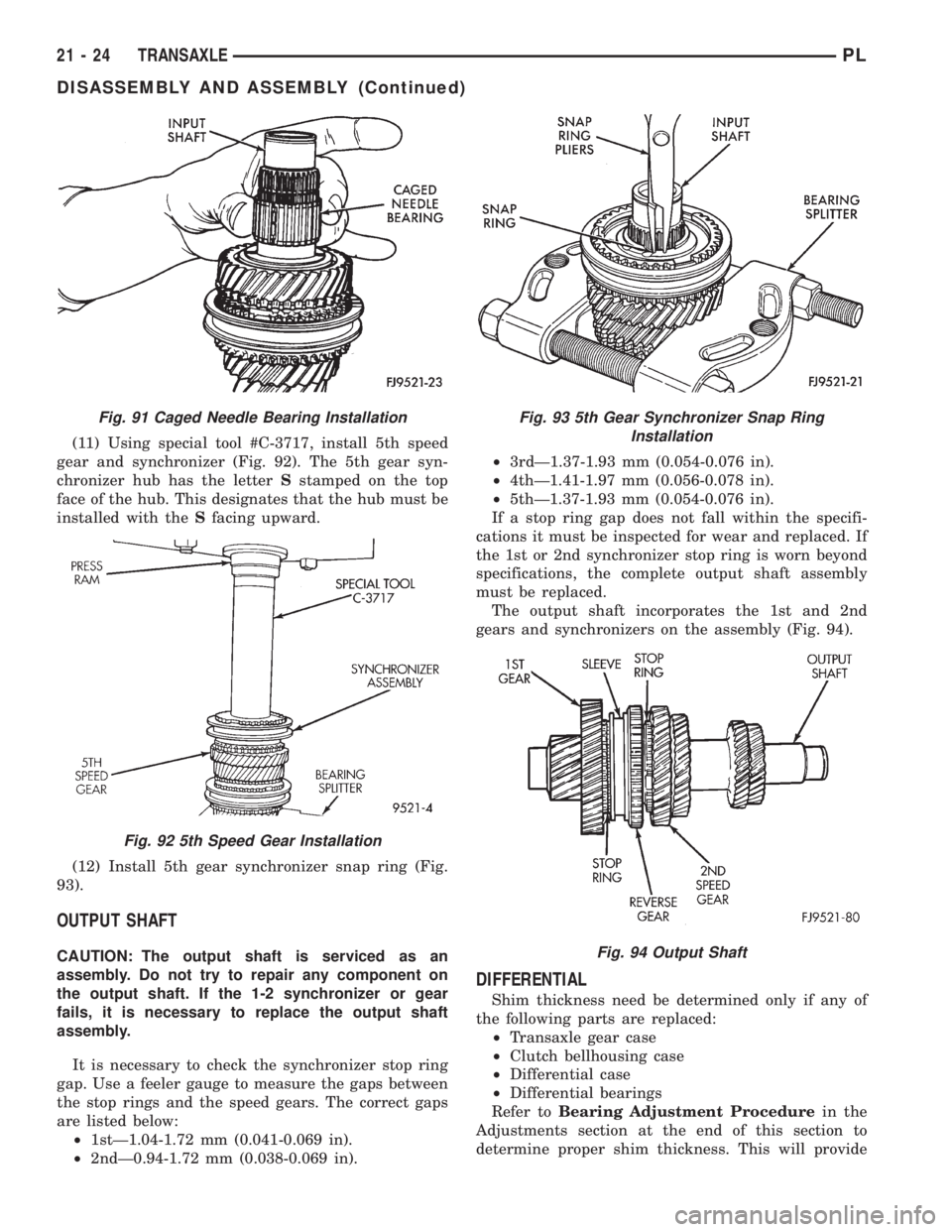
(11) Using special tool #C-3717, install 5th speed
gear and synchronizer (Fig. 92). The 5th gear syn-
chronizer hub has the letterSstamped on the top
face of the hub. This designates that the hub must be
installed with theSfacing upward.
(12) Install 5th gear synchronizer snap ring (Fig.
93).
OUTPUT SHAFT
CAUTION: The output shaft is serviced as an
assembly. Do not try to repair any component on
the output shaft. If the 1-2 synchronizer or gear
fails, it is necessary to replace the output shaft
assembly.
It is necessary to check the synchronizer stop ring
gap. Use a feeler gauge to measure the gaps between
the stop rings and the speed gears. The correct gaps
are listed below:
²1stÐ1.04-1.72 mm (0.041-0.069 in).
²2ndÐ0.94-1.72 mm (0.038-0.069 in).²3rdÐ1.37-1.93 mm (0.054-0.076 in).
²4thÐ1.41-1.97 mm (0.056-0.078 in).
²5thÐ1.37-1.93 mm (0.054-0.076 in).
If a stop ring gap does not fall within the specifi-
cations it must be inspected for wear and replaced. If
the 1st or 2nd synchronizer stop ring is worn beyond
specifications, the complete output shaft assembly
must be replaced.
The output shaft incorporates the 1st and 2nd
gears and synchronizers on the assembly (Fig. 94).
DIFFERENTIAL
Shim thickness need be determined only if any of
the following parts are replaced:
²Transaxle gear case
²Clutch bellhousing case
²Differential case
²Differential bearings
Refer toBearing Adjustment Procedurein the
Adjustments section at the end of this section to
determine proper shim thickness. This will provide
Fig. 91 Caged Needle Bearing Installation
Fig. 92 5th Speed Gear Installation
Fig. 93 5th Gear Synchronizer Snap Ring
Installation
Fig. 94 Output Shaft
21 - 24 TRANSAXLEPL
DISASSEMBLY AND ASSEMBLY (Continued)
Page 968 of 1200
correct bearing preload and proper bearing turning
torque.
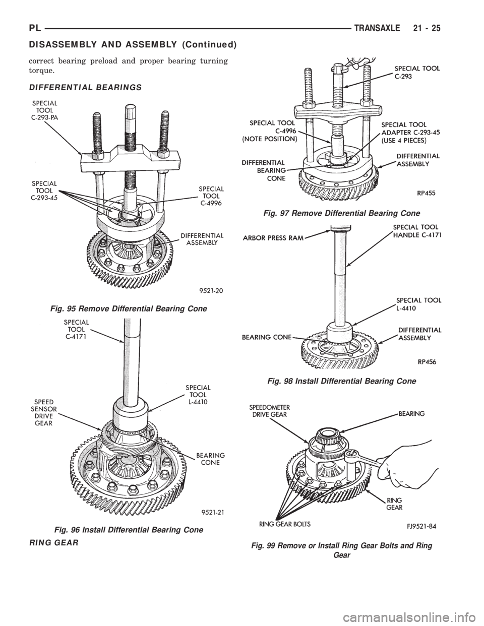
DIFFERENTIAL BEARINGS
RING GEAR
Fig. 95 Remove Differential Bearing Cone
Fig. 96 Install Differential Bearing Cone
Fig. 97 Remove Differential Bearing Cone
Fig. 98 Install Differential Bearing Cone
Fig. 99 Remove or Install Ring Gear Bolts and Ring
Gear
PLTRANSAXLE 21 - 25
DISASSEMBLY AND ASSEMBLY (Continued)
Page 969 of 1200
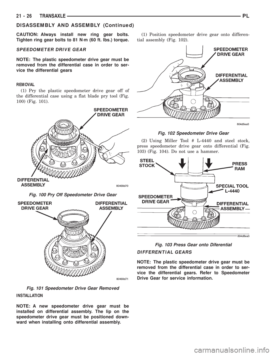
CAUTION: Always install new ring gear bolts.
Tighten ring gear bolts to 81 N´m (60 ft. lbs.) torque.
SPEEDOMETER DRIVE GEAR
NOTE: The plastic speedometer drive gear must be
removed from the differential case in order to ser-
vice the differential gears
REMOVAL
(1) Pry the plastic speedometer drive gear off of
the differential case using a flat blade pry tool (Fig.
100) (Fig. 101).
INSTALLATION
NOTE: A new speedometer drive gear must be
installed on differential assembly. The lip on the
speedometer drive gear must be positioned down-
ward when installing onto differential assembly.(1) Position speedometer drive gear onto differen-
tial assembly (Fig. 102).
(2) Using Miller Tool # L-4440 and steel stock,
press speedometer drive gear onto differential (Fig.
103) (Fig. 104). Do not use a hammer.
DIFFERENTIAL GEARS
NOTE: The plastic speedometer drive gear must be
removed from the differential case in order to ser-
vice the differential gears. Refer to Speedometer
Drive Gear for service information.
Fig. 100 Pry Off Speedometer Drive Gear
Fig. 101 Speedometer Drive Gear Removed
Fig. 102 Speedometer Drive Gear
Fig. 103 Press Gear onto Diferential
21 - 26 TRANSAXLEPL
DISASSEMBLY AND ASSEMBLY (Continued)
Page 970 of 1200
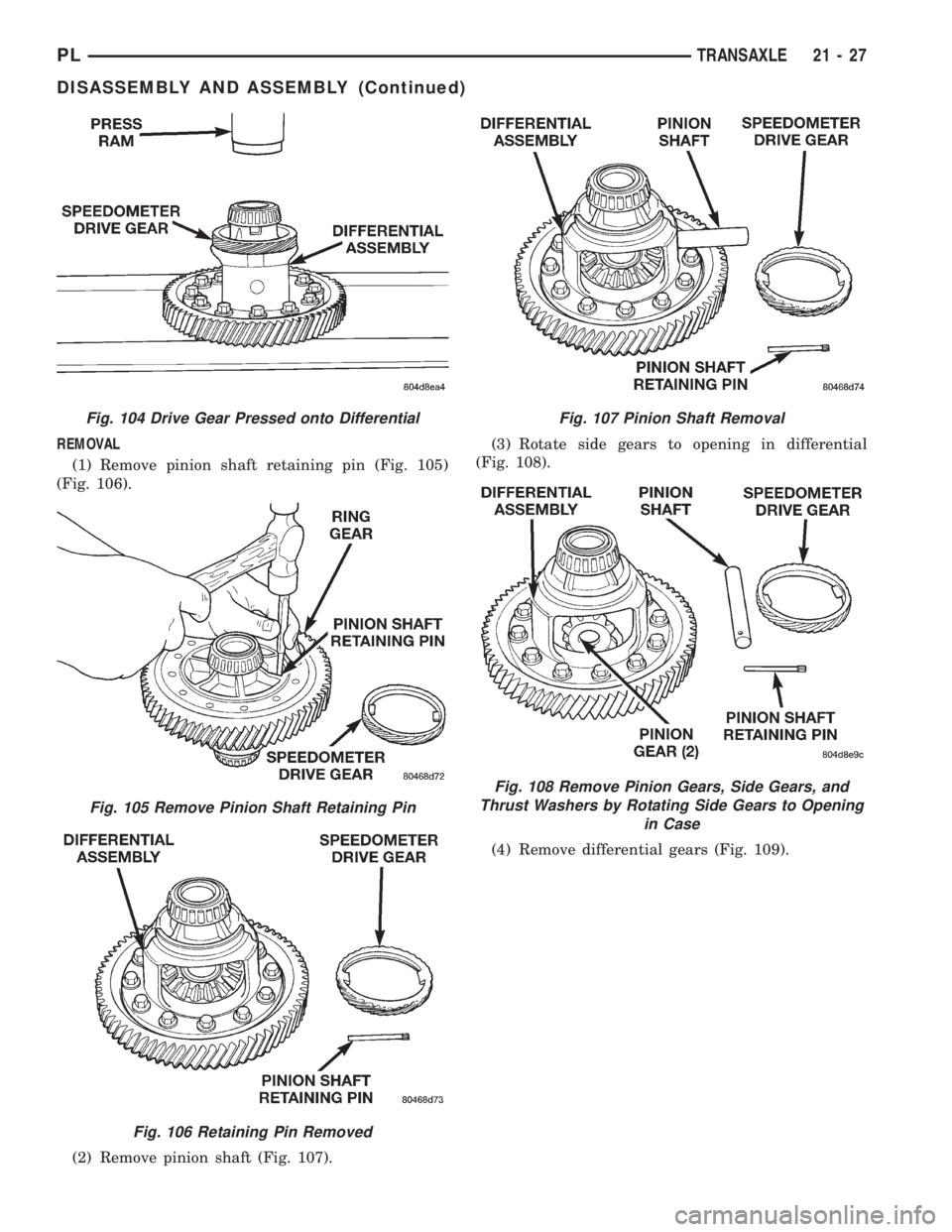
REMOVAL
(1) Remove pinion shaft retaining pin (Fig. 105)
(Fig. 106).
(2) Remove pinion shaft (Fig. 107).(3) Rotate side gears to opening in differential
(Fig. 108).
(4) Remove differential gears (Fig. 109).
Fig. 104 Drive Gear Pressed onto Differential
Fig. 105 Remove Pinion Shaft Retaining Pin
Fig. 106 Retaining Pin Removed
Fig. 107 Pinion Shaft Removal
Fig. 108 Remove Pinion Gears, Side Gears, and
Thrust Washers by Rotating Side Gears to Opening
in Case
PLTRANSAXLE 21 - 27
DISASSEMBLY AND ASSEMBLY (Continued)