ISUZU KB P190 2007 Workshop Repair Manual
Manufacturer: ISUZU, Model Year: 2007, Model line: KB P190, Model: ISUZU KB P190 2007Pages: 6020, PDF Size: 70.23 MB
Page 3971 of 6020
TRANSMISSION CONTROL SYSTEM (AW30–40LE) 7A2-5
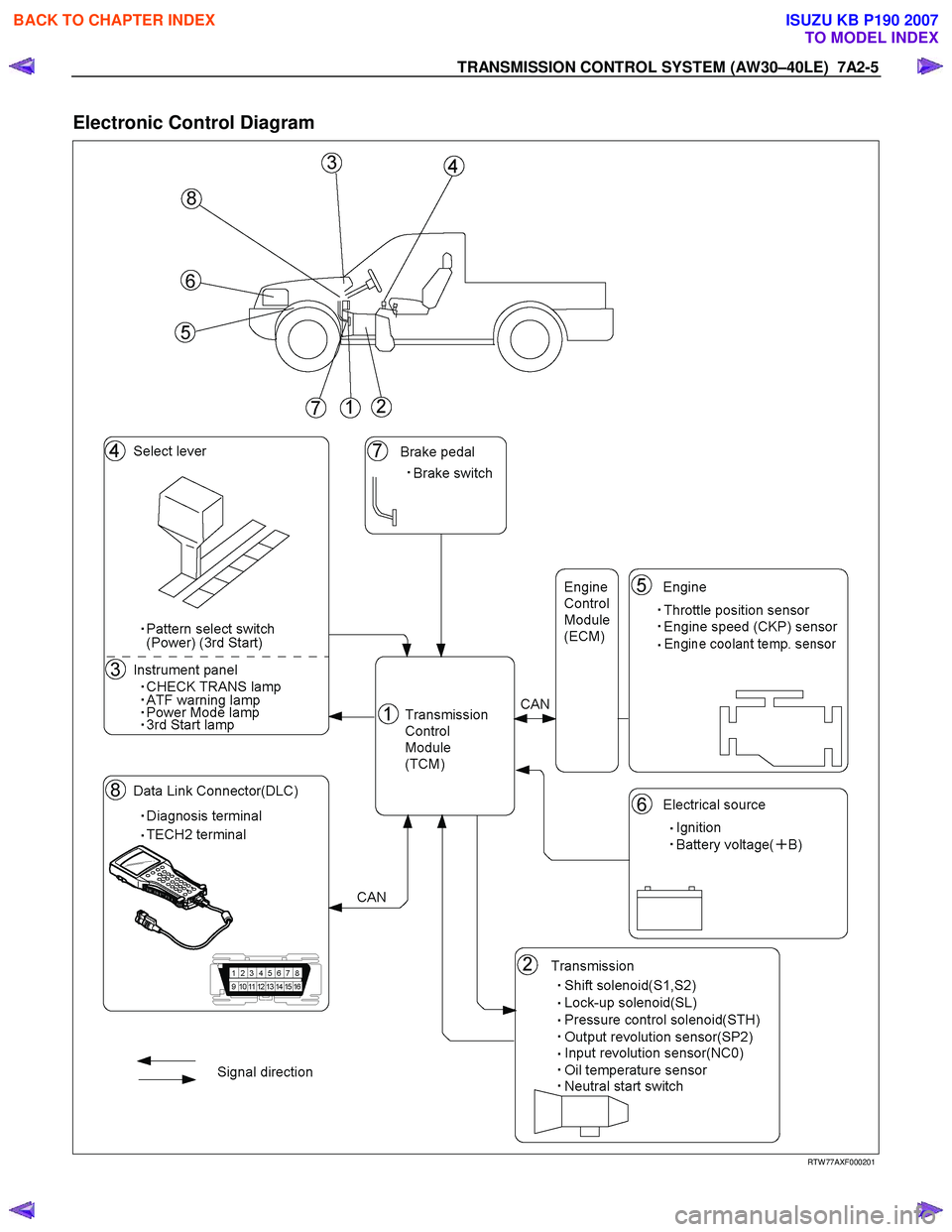
Electronic Control Diagram
RTW 77AXF000201
BACK TO CHAPTER INDEX
TO MODEL INDEX
ISUZU KB P190 2007
Page 3972 of 6020
7A2-6 TRANSMISSION CONTROL SYSTEM (AW30–40LE)
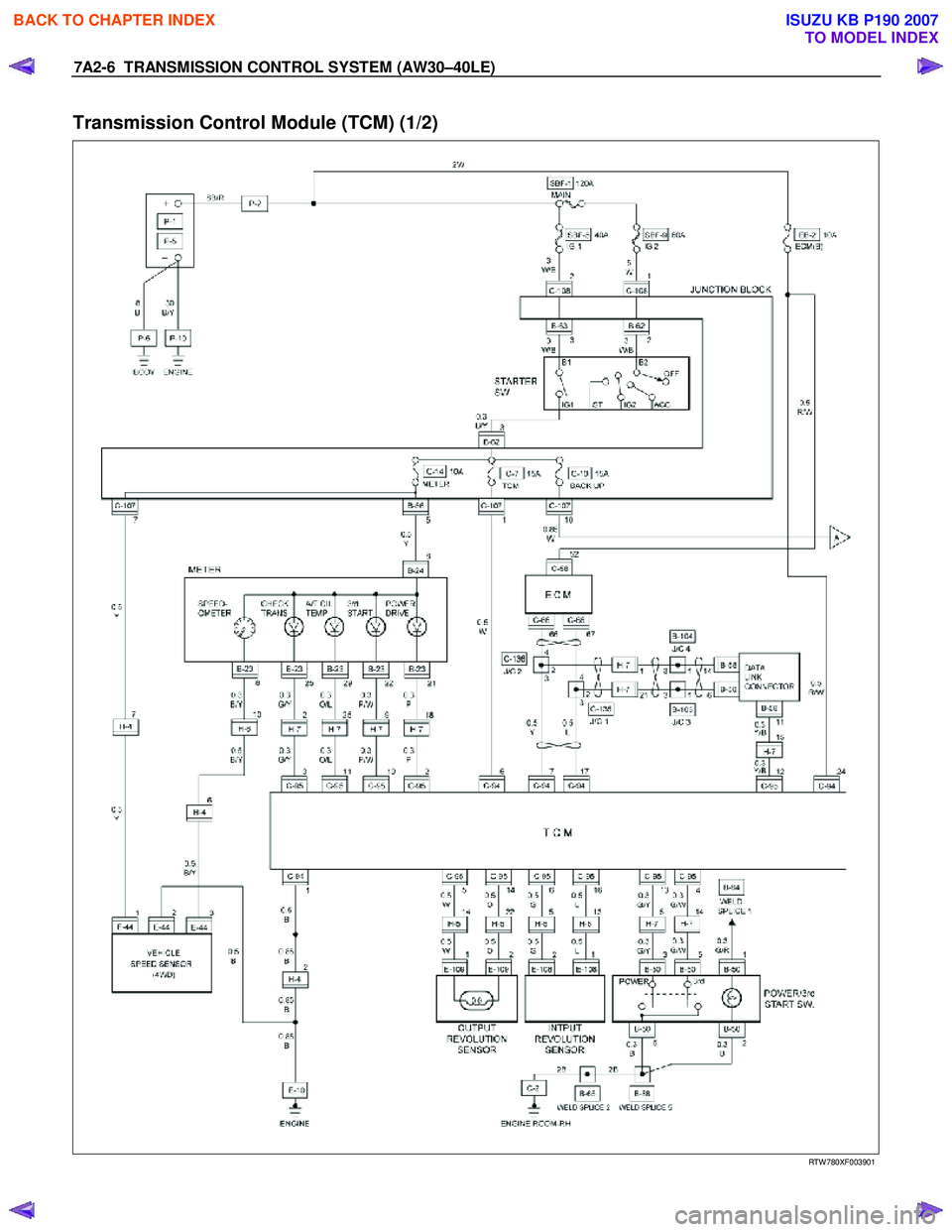
Transmission Control Module (TCM) (1/2)
RTW 780XF003901
BACK TO CHAPTER INDEX
TO MODEL INDEX
ISUZU KB P190 2007
Page 3973 of 6020
TRANSMISSION CONTROL SYSTEM (AW30–40LE) 7A2-7
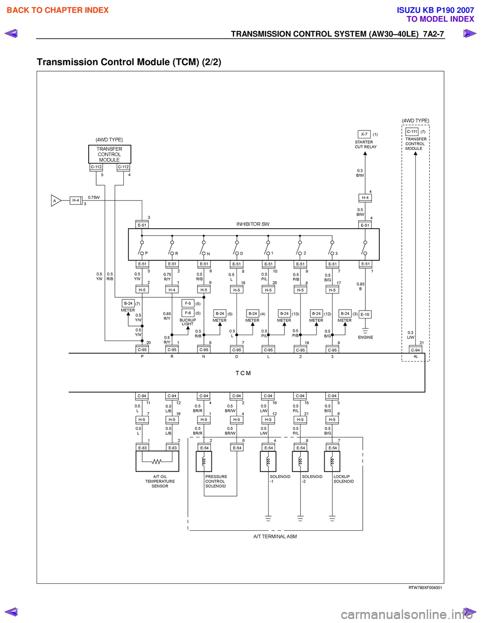
Transmission Control Module (TCM) (2/2)
RTW 780XF004001
BACK TO CHAPTER INDEX
TO MODEL INDEX
ISUZU KB P190 2007
Page 3974 of 6020

7A2-8 TRANSMISSION CONTROL SYSTEM (AW30–40LE)
TCM Point Table
RTW 77ASF000401
C-94 Connector
PIN No. SIGNAL NAME
A1 GND
A2 PRESSURE CONTROL SOLENOID GND
A3 —
A4 PRESSURE CONTROL SOLENOID
A5 L-up SOLENOID
A6 STARTER SW (IG1)
A7 CAN COMMUNICATION (-)
A8 —
A9 —
A10 —
A11 T/M OIL TEMPERATURE SENSOR
A12 T/M OIL TEMPERATURE SENSOR GND
A13 —
A14 —
A15 SHIFT SOLENOID (S2)
A16 SHIFT SOLENOID (S1)
A17 CAN COMMUNICATION (+)
A18 —
A19 —
A20 —
A21 —
A22 —
A23 GND
A24 BATTERY
C-95 Connector
PIN No. SIGNAL NAME
B1 NEUTRAL START SW (R)
B2 POW ER LAMP
B3 CHECK TRANS LAMP
B4 PATTERN SELECT SW (3rd START)
B5 SPEED SENSOR (+)
B6 INPUT REVOLUTION SENSOR (+)
B7 NEUTRAL START SW (D)
B8 NEUTRAL START SW (N)
B9 NEUTRAL START SW (3)
B10 3rd START LAMP
B11 OIL TEMPERATURE W ARNING LAMP
B12 DIAGNOSIS TERMINAL
B13 PATTERN SELECT SW (POW ER)
B14 SPEED SENSOR (-)
B15 —
B16 INPUT REVOLUTION SENSOR (+)
B17 —
B18 NEUTRAL START SW (L)
B19 NEUTRAL START SW (2)
B20 NEUTRAL START SW (P)
B21 TRANSMISFER LOW 4 SW
B22 BRAKE LAMP SW
B23 DIAGNOSIS OUT PUT
B24 —
B25 —
B26 —
BACK TO CHAPTER INDEX
TO MODEL INDEX
ISUZU KB P190 2007
Page 3975 of 6020

TRANSMISSION CONTROL SYSTEM (AW30–40LE) 7A2-9
TCM Voltage & Resistance Check Sheet
CHECK ITEM PIN No. VALUE NOTE
VIGN C-94: 6–1 VIGN Key “ON”
Backup Power Supply C-94: 24–1 +B (Always) Key “ON”
Neutral Start Switch P “P” Position VIGN Key “ON”
Except “P” 0V
Neutral Start Switch R C-95: 1–C-94: 1 “R” Position VIGN Key “ON”
Except “R” 0V
Neutral Start Switch N C-95: 8–C-94: 1 “N” Position VIGN Key “ON”
Except “N” 0V
Neutral Start Switch D C95: 7–C-94: 1 “D” Position VIGN Key “ON”
Except “D” 0V
Neutral Start Switch 2 C-95: 19–C-94: 1 “2” Position VIGN Key “ON”
Except “2” 0V
Neutral Start Switch 1 C-95: 18–C-94: 1 “1” Position VIGN Key “ON”
Except “1” 0V
Neutral Start Switch 3 C-95: 9–C-94: 1 “3” Position VIGN Key “ON”
Except “3” 0V
Power SW C-95: 13–C-94: 1 “ON” 0V Key “ON”
“OFF” VIGN
3rd Start SW C-95: 4–C-94: 1 “ON” 0V Key “ON”
“OFF” VIGN
Brake SW C-95: 22–C-94: 1 “ON” VIGN Key “ON”
“OFF” 0V
AT Oil Temperature
Sensor C-94: 11–12 20
°C/68 °F 4.6V Engine run.
155°C/311 °F 1.1V
4L Signal C-95: 21–C-94: 1 4L 0V Key “ON”
2H/4H VIGN
Diag SW C-95: 12–C-94: 1 “ON” VIGN Key “ON”
“OFF” 0V
Shift Solenoid A (S1) C-94: 16–1 P VIGN Engine run.
R VIGN
N VIGN
D–1 VIGN
D–2 VIGN
D–3 0V
D–4 0V
BACK TO CHAPTER INDEX
TO MODEL INDEX
ISUZU KB P190 2007
Page 3976 of 6020
7A2-10 TRANSMISSION CONTROL SYSTEM (AW30–40LE)
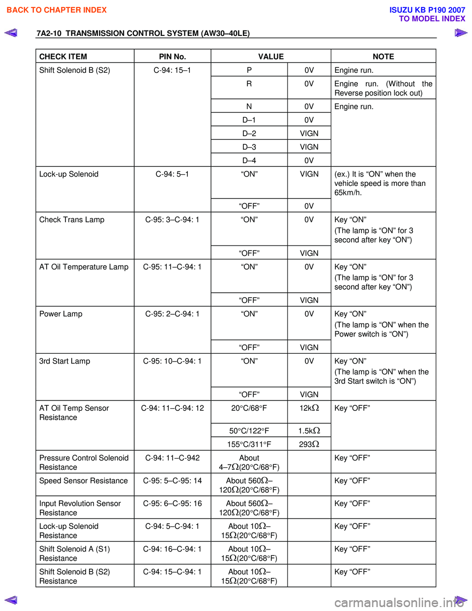
CHECK ITEM PIN No. VALUE NOTE
Shift Solenoid B (S2) C-94: 15–1 P 0V Engine run.
R 0V Engine run. (W ithout the
Reverse position lock out)
N 0V Engine run.
D–1 0V
D–2 VIGN
D–3 VIGN
D–4 0V
Lock-up Solenoid C-94: 5–1 “ON” VIGN (ex.) It is “ON” when the
vehicle speed is more than
65km/h.
“OFF” 0V
Check Trans Lamp C-95: 3–C-94: 1 “ON” 0V Key “ON”
(The lamp is “ON” for 3
second after key “ON”)
“OFF” VIGN
AT Oil Temperature Lamp C-95: 11–C-94: 1 “ON” 0V Key “ON”
(The lamp is “ON” for 3
second after key “ON”)
“OFF” VIGN
Power Lamp C-95: 2–C-94: 1 “ON” 0V Key “ON”
(The lamp is “ON” when the
Power switch is “ON”)
“OFF” VIGN
3rd Start Lamp C-95: 10–C-94: 1 “ON” 0V Key “ON”
(The lamp is “ON” when the
3rd Start switch is “ON”)
“OFF” VIGN
AT Oil Temp Sensor
Resistance C-94: 11–C-94: 12 20
°C/68 °F 12kΩ Key “OFF”
50°C/122 °F 1.5kΩ
155°C/311 °F 293Ω
Pressure Control Solenoid
Resistance C-94: 11–C-942 About
4–7
Ω(20 °C/68 °F)
Key “OFF”
Speed Sensor Resistance C-95: 5–C-95: 14 About 560Ω–
120
Ω(20 °C/68 °F)
Key “OFF”
Input Revolution Sensor
Resistance C-95: 6–C-95: 16 About 560Ω–
120
Ω(20 °C/68 °F)
Key “OFF”
Lock-up Solenoid
Resistance C-94: 5–C-94: 1 About 10Ω–
15
Ω(20 °C/68 °F)
Key “OFF”
Shift Solenoid A (S1)
Resistance C-94: 16–C-94: 1 About 10Ω–
15
Ω(20 °C/68 °F)
Key “OFF”
Shift Solenoid B (S2)
Resistance C-94: 15–C-94: 1 About 10Ω–
15
Ω(20 °C/68 °F)
Key “OFF”
BACK TO CHAPTER INDEX
TO MODEL INDEX
ISUZU KB P190 2007
Page 3977 of 6020
TRANSMISSION CONTROL SYSTEM (AW30–40LE) 7A2-11
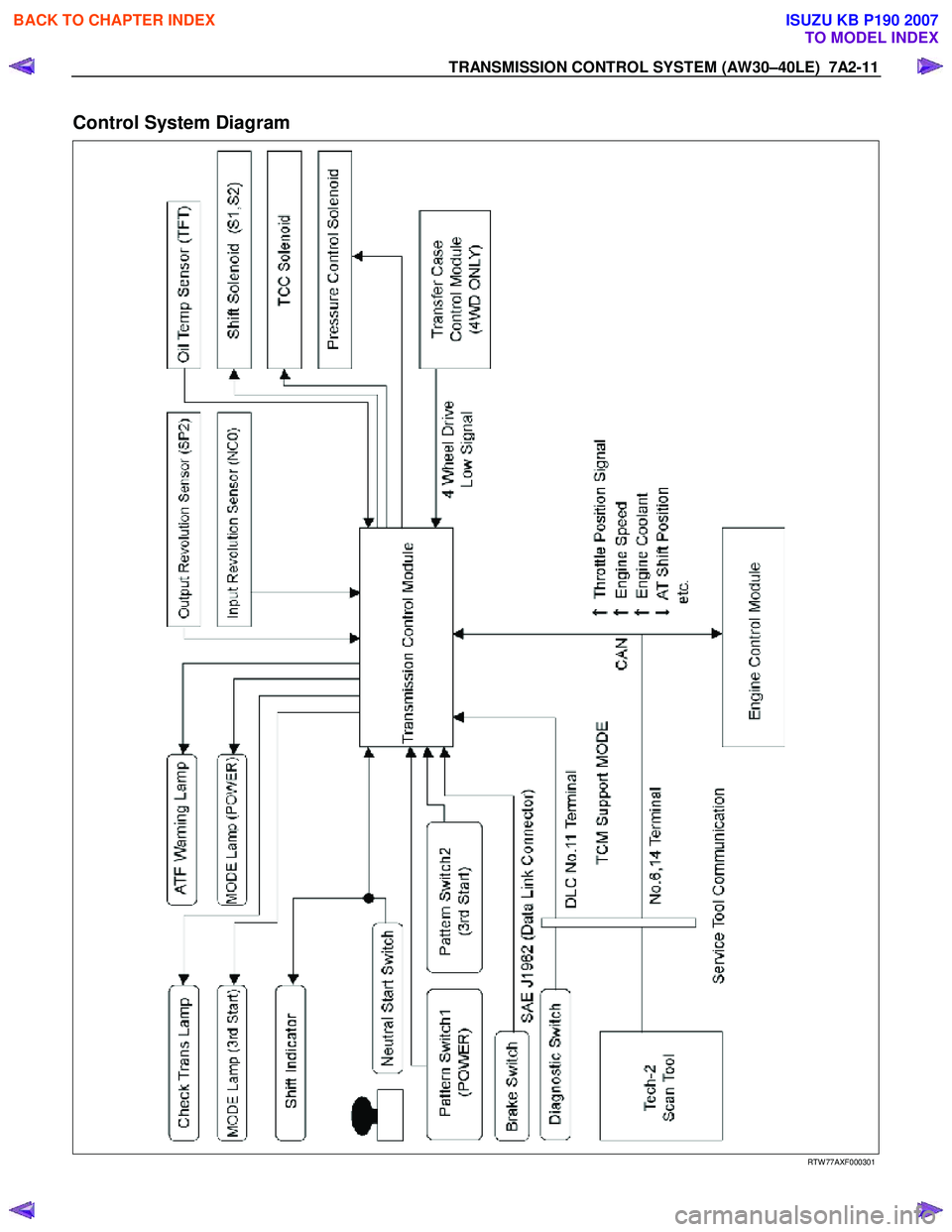
Control System Diagram
RTW 77AXF000301
BACK TO CHAPTER INDEX
TO MODEL INDEX
ISUZU KB P190 2007
Page 3978 of 6020
7A2-12 TRANSMISSION CONTROL SYSTEM (AW30–40LE)
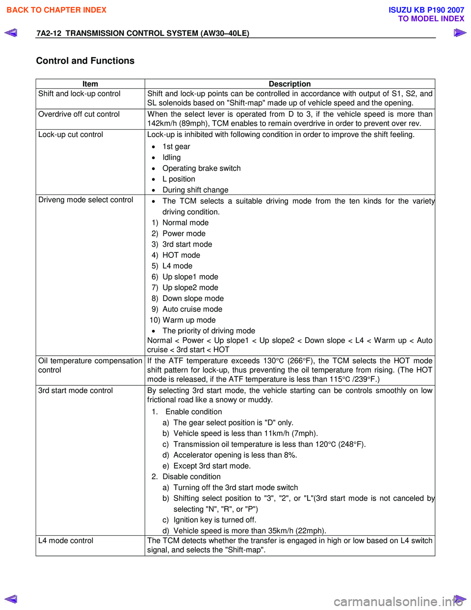
Control and Functions
Item Description
Shift and lock-up control Shift and lock-up points can be controlled in accordance with output of S1, S2, and SL solenoids based on "Shift-map" made up of vehicle speed and the opening.
Overdrive off cut control W hen the select lever is operated from D to 3, if the vehicle speed is more than 142km/h (89mph), TCM enables to remain overdrive in order to prevent over rev.
Lock-up cut control Lock-up is inhibited with following condition in order to improve the shift feeling.
• 1st gear
• Idling
• Operating brake switch
• L position
• During shift change
Driveng mode select control
• The TCM selects a suitable driving mode from the ten kinds for the variety
driving condition.
1) Normal mode
2) Power mode
3) 3rd start mode
4) HOT mode
5) L4 mode
6) Up slope1 mode
7) Up slope2 mode
8) Down slope mode
9) Auto cruise mode
10) W arm up mode • The priority of driving mode
Normal < Power < Up slope1 < Up slope2 < Down slope < L4 < W arm up < Auto
cruise < 3rd start < HOT
Oil temperature compensation
control If the ATF temperature exceeds 130
°C (266 °F), the TCM selects the HOT mode
shift pattern for lock-up, thus preventing the oil temperature from rising. (The HOT
mode is released, if the ATF temperature is less than 115 °C /239 °F.)
3rd start mode control By selecting 3rd start mode, the vehicle starting can be controls smoothly on low
frictional road like a snowy or muddy.
1. Enable condition a) The gear select position is "D" only.
b) Vehicle speed is less than 11km/h (7mph).
c) Transmission oil temperature is less than 120 °C (248 °F).
d) Accelerator opening is less than 8%.
e) Except 3rd start mode.
2. Disable condition a) Turning off the 3rd start mode switch
b) Shifting select position to "3", "2", or "L"(3rd start mode is not canceled b
y
selecting "N", "R", or "P")
c) Ignition key is turned off.
d) Vehicle speed is more than 35km/h (22mph).
L4 mode control The TCM detects whether the transfer is engaged in high or low based on L4 switch
signal, and selects the "Shift-map".
BACK TO CHAPTER INDEX
TO MODEL INDEX
ISUZU KB P190 2007
Page 3979 of 6020

TRANSMISSION CONTROL SYSTEM (AW30–40LE) 7A2-13
Item Description
Reverse lock out control If the select lever is moved to "R" position during forward driving, the TCM prohibits
reverse driving by turn off the S1 and turn on the S2 for prevention of danger and
protection of the automatic transmission.
1. Enable condition a) Vehicle speed is more than 11km/h (7mph).
2. Disable condition a) Vehicle speed is less than 9km/h (6mph).
b) W hen except "R" position is detected.
Auto cruise mode control If the auto cruise control can’t keep the setting speed like a uphill driving, the TCM selects the auto cruise mode shift pattern for downshifting, thus keeping the vehicle
speed.
W arm-up mode control TCM selects the warm-up mode shift pattern in engine cold condition for improvement of drivability and facilitation of warm-up.
Squat control W hen the TCM detects N→D garage shift, the TCM controls 1-3-1 shift by setting
timer, in order to improve the shift feel at N →D.
Coast down control The TCM switches to the coast down control at the coasting, in order to reduce the
roughness of shifting.
Uphill control W hen the TCM detected uphill, the TCM automatically switches to the uphill mode
in two-stage in proportion to inclination pitch to prevent the busy shifting and to
obtain an enough torque.
Downhill control W hen the TCM detected downhill, the TCM automatically switches to the downhill
mode, and shifts to the 3rd or keeps in the 3rd in order to prevent the vehicle
acceleration. Then, the brake load is reduced by a moderate engine brake and fuel
consumption is improved by the fuel cut.
Line pressure control The TCM controls the impressed current of the pressure control solenoid based on the throttle opening, and regulates suitable throttle pressure.
Engine truque management
control The TCM controls engine torque for improvement of shift quality or durability under
the following conditions.
• Upshift and downshift
• Garageshift
Indicate driving mode function The TCM indicates the following driving mode on instrument panel.
• Power mode
• 3rd start mode
Indicate oil temperature
warning function If the transmission oil temperature sensor senses that transmission oil temperature
is greater than 146 °C (295 °F) , the TCM turns on ATF warning lamp. (The warning
lamp is turned off, if oil temperature is less than 126 °C/ 259 °F .)
Fail-safe function W hen trouble occurs to vehicle sensor and each solenoid, TCM automatically exerts
fail-safe control not to spoil driveability.
• This control is exerted when sensor or actuator is in trouble, while TCM works
normally.
• The "CHECK TRANS" light flashes to alert the driver, and the transmission
must be manually shifted as follows.
Select lever position Gear position
D 4 (Fourth)
3 4 (Fourth)
2 3 (Third)
L 3 (Third)
R Reverse
Shift are firmer to prevent clutch slip and consequent wear. The fault should be
corrected as soon as possible.
BACK TO CHAPTER INDEX
TO MODEL INDEX
ISUZU KB P190 2007
Page 3980 of 6020

7A2-14 TRANSMISSION CONTROL SYSTEM (AW30–40LE)
Item Description
Diagnosis function
• If there is an abnormality in vehicle sensors, each solenoid (S1, S2, SL, STH),
or throttle position sensor, "CHECK TRANS" lamp is actuated to warn the drive.
But when the abnormality items have been restored to normal, the light does
not blink.
• Faulty parts are memorized in TCM. If self-diagnosis start signal is inputted,
"CHECK TRANS" lamp is blinked and results of diagnosis are indicated. A
history of faults remains recorded even when IGN switch is off. If DG1 switch
signal is inputted, or by using F1: Clear DTC Information for TECH 2, the
records can be erased.
TECH 2
• Output of control data in the TCM
• Actuator (Solenoid) operation check
• Erasure of trouble code
• Output of DTC code
BACK TO CHAPTER INDEX
TO MODEL INDEX
ISUZU KB P190 2007