ISUZU KB P190 2007 Workshop Repair Manual
Manufacturer: ISUZU, Model Year: 2007, Model line: KB P190, Model: ISUZU KB P190 2007Pages: 6020, PDF Size: 70.23 MB
Page 731 of 6020
5C-32 BRAKES
5. Pull the PEDAL ARM a little towards you so that the
PEDAL ARM is not pushed in.
6. Holding the PEDAL ARM still with one hand, push in the whole SW ITCH with the other hand until the PLUNGER
of the SW ITCH is pushed in and the SW ITCH itself hits
the RUBBER of the PEDAL ARM.
In this condition, turn the SW ITCH clock-wise until a “click” sound is heard and lock it.
By doing this the SW ITCH is adjusted at 0.7 ±0.5 mm
(0.028 ± 0.020 in) clearance.
BACK TO CHAPTER INDEX
TO MODEL INDEX
ISUZU KB P190 2007
Page 732 of 6020
BRAKES 5C-33
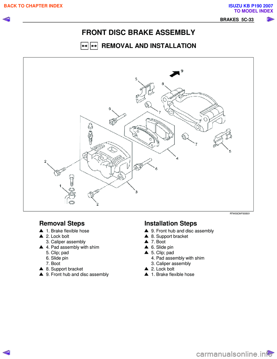
FRONT DISC BRAKE ASSEMBLY
REMOVAL AND INSTALLATION
RTW 55CMF000501
Removal Steps
1. Brake flexible hose
2. Lock bolt
3. Caliper assembly
4. Pad assembly with shim
5. Clip; pad
6. Slide pin
7. Boot
8. Support bracket
9. Front hub and disc assembly
Installation Steps
9. Front hub and disc assembly
8. Support bracket
7. Boot
6. Slide pin
5. Clip; pad
4. Pad assembly with shim
3. Caliper assembly
2. Lock bolt
1. Brake flexible hose
BACK TO CHAPTER INDEX
TO MODEL INDEX
ISUZU KB P190 2007
Page 733 of 6020
5C-34 BRAKES
RUW 55CSH000101
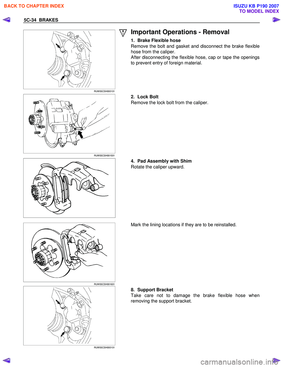
Important Operations - Removal
1. Brake Flexible hose
Remove the bolt and gasket and disconnect the brake flexible
hose from the caliper.
After disconnecting the flexible hose, cap or tape the openings
to prevent entry of foreign material.
RUW 55CSH001501
2. Lock Bolt
Remove the lock bolt from the caliper.
4. Pad Assembly with Shim
Rotate the caliper upward.
RUW 55CSH001601
Mark the lining locations if they are to be reinstalled.
RUW 55CSH000101
8. Support Bracket
Take care not to damage the brake flexible hose when
removing the support bracket.
BACK TO CHAPTER INDEX
TO MODEL INDEX
ISUZU KB P190 2007
Page 734 of 6020
BRAKES 5C-35
9. Front Hub and Disc Assembly
For the removal procedure, refer to Section 4C “FRONT
W HEEL DRIVE”.
Important Operations - Installation
9. Front Hub and Disc Assembly
For the installation procedure, refer to the front hub and disc
reassembly procedure in Section 4C “FRONT W HEEL
DRIVE”.
RUW 55CSH000101
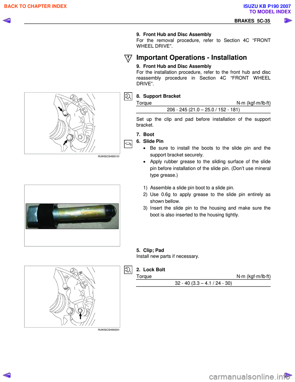
8. Support Bracket
Torque N ⋅m (kgf ⋅m/lb ⋅ft)
206 - 245 (21.0 – 25.0 / 152 - 181)
Set up the clip and pad before installation of the support
bracket.
7. Boot
6. Slide Pin • Be sure to install the boots to the slide pin and the
support bracket securely.
•
Apply rubber grease to the sliding surface of the slide
pin before installation of the slide pin. (Don’t use mineral
type grease.)
1) Assemble a slide pin boot to a slide pin.
2) Use 0.6g to apply grease to the slide pin entirely as shown bellow.
3) Insert the slide pin to the housing and make sure the boot is also inserted to the housing tightly.
5. Clip; Pad
Install new parts if necessary.
RUW 55CSH000201
2. Lock Bolt
Torque N ⋅m (kgf ⋅m/lb ⋅ft)
32 - 40 (3.3 – 4.1 / 24 - 30)
BACK TO CHAPTER INDEX
TO MODEL INDEX
ISUZU KB P190 2007
Page 735 of 6020
5C-36 BRAKES
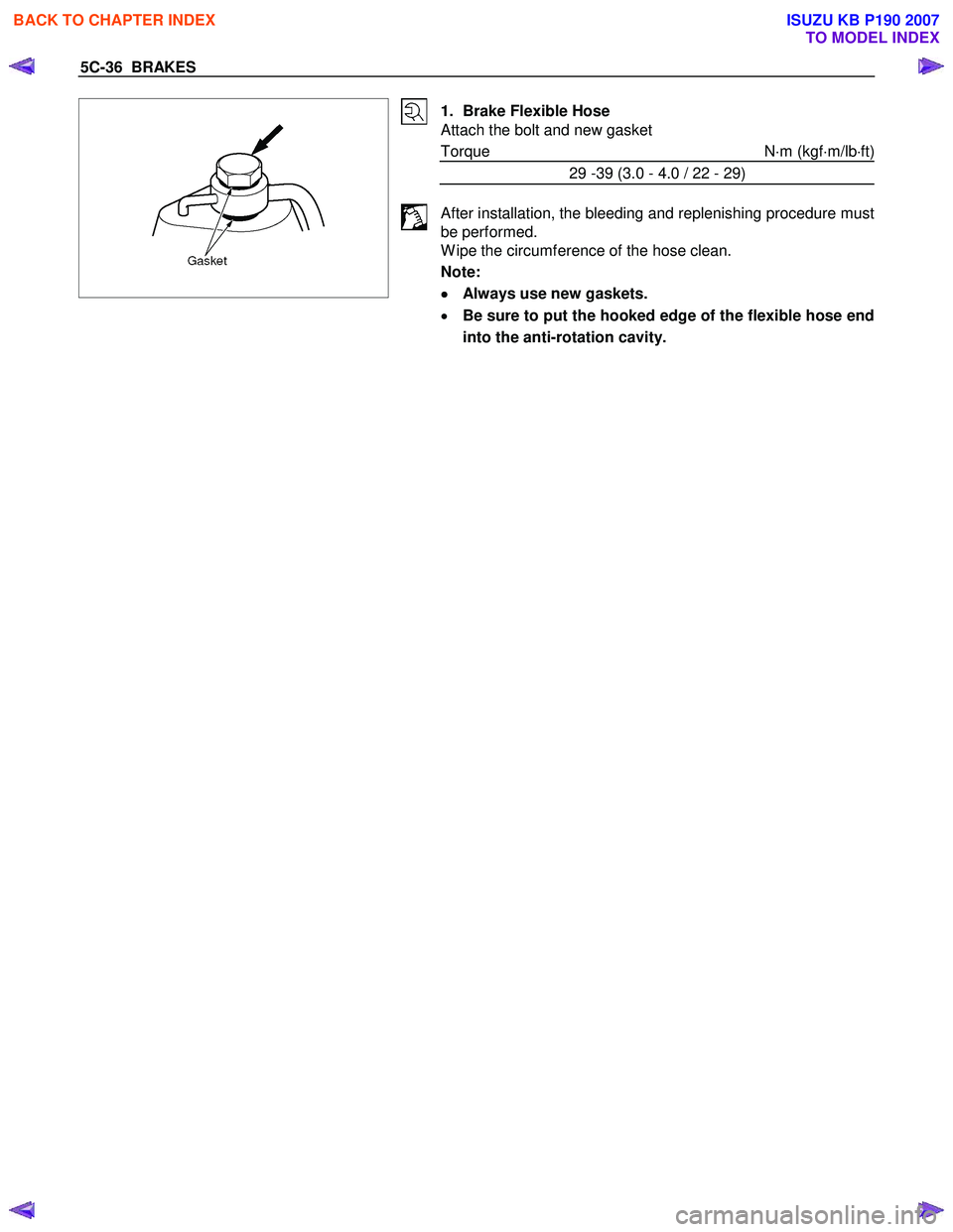
1. Brake Flexible Hose
Attach the bolt and new gasket
Torque N ⋅m (kgf ⋅m/lb ⋅ft)
29 -39 (3.0 - 4.0 / 22 - 29)
After installation, the bleeding and replenishing procedure must
be performed.
W ipe the circumference of the hose clean.
Note:
•
••
•
Always use new gaskets.
• Be sure to put the hooked edge of the flexible hose end
into the anti-rotation cavity.
BACK TO CHAPTER INDEX
TO MODEL INDEX
ISUZU KB P190 2007
Page 736 of 6020
BRAKES 5C-37
REMOVAL AND INSTALLATION OF DISC PAD
RUW 55CSH001501
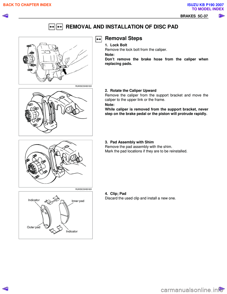
Removal Steps
1. Lock Bolt
Remove the lock bolt from the caliper.
Note:
Don’t remove the brake hose from the caliper when
replacing pads.
2. Rotate the Caliper Upward
Remove the caliper from the support bracket and move the
caliper to the upper link or the frame.
Note:
While caliper is removed from the support bracket, neve
r
step on the brake pedal or the piston will protrude rapidly.
RUW 55CSH001601
3. Pad Assembly with Shim
Remove the pad assembly with the shim.
Mark the pad locations if they are to be reinstalled.
4. Clip; Pad
Discard the used clip and install a new one.
BACK TO CHAPTER INDEX
TO MODEL INDEX
ISUZU KB P190 2007
Page 737 of 6020
5C-38 BRAKES
Installation Steps
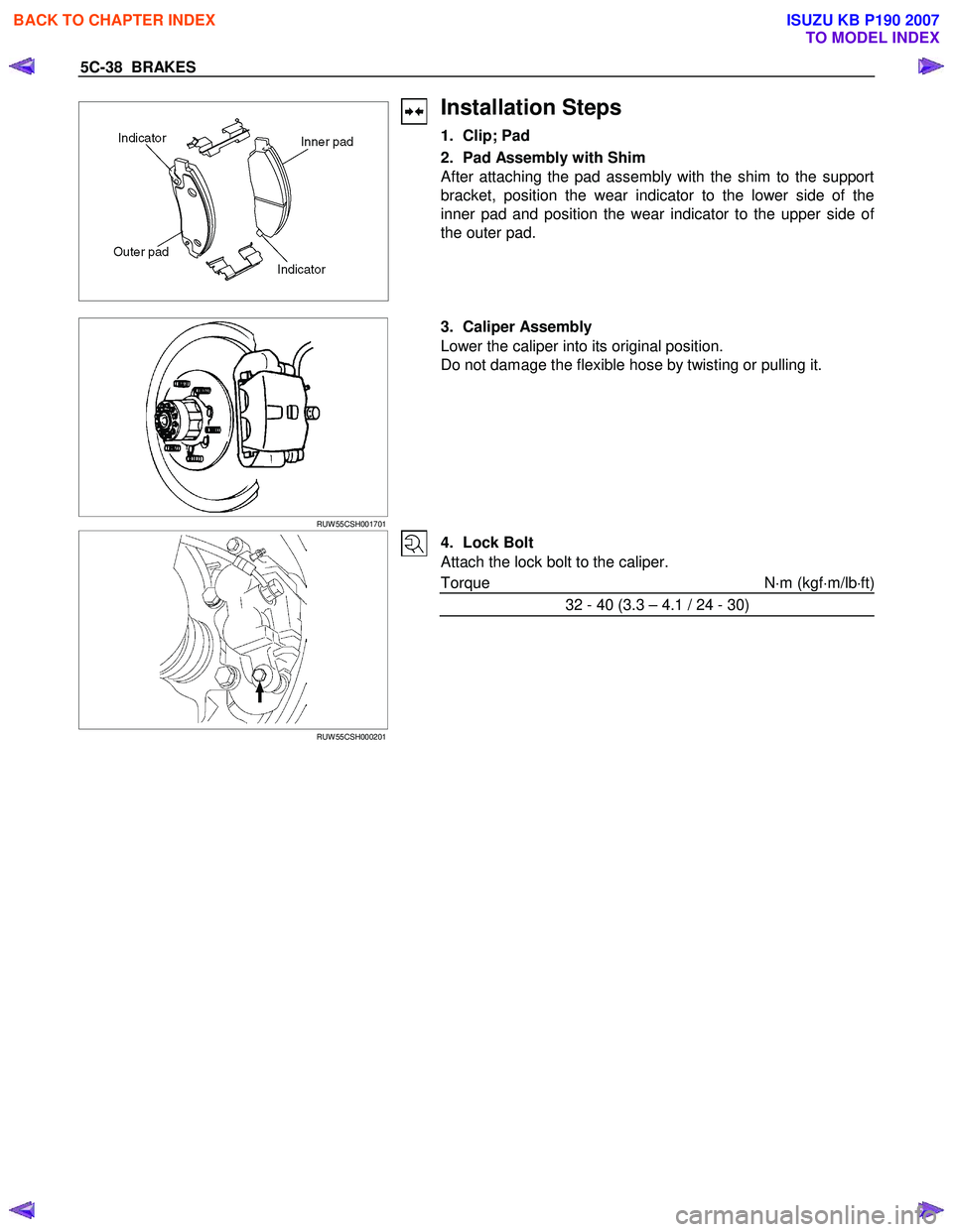
1. Clip; Pad
2. Pad Assembly with Shim
After attaching the pad assembly with the shim to the support
bracket, position the wear indicator to the lower side of the
inner pad and position the wear indicator to the upper side o
f
the outer pad.
RUW 55CSH001701
3. Caliper Assembly
Lower the caliper into its original position.
Do not damage the flexible hose by twisting or pulling it.
RUW 55CSH000201
4. Lock Bolt
Attach the lock bolt to the caliper.
Torque N ⋅m (kgf ⋅m/lb ⋅ft)
32 - 40 (3.3 – 4.1 / 24 - 30)
BACK TO CHAPTER INDEX
TO MODEL INDEX
ISUZU KB P190 2007
Page 738 of 6020
BRAKES 5C-39
DISASSEMBLY
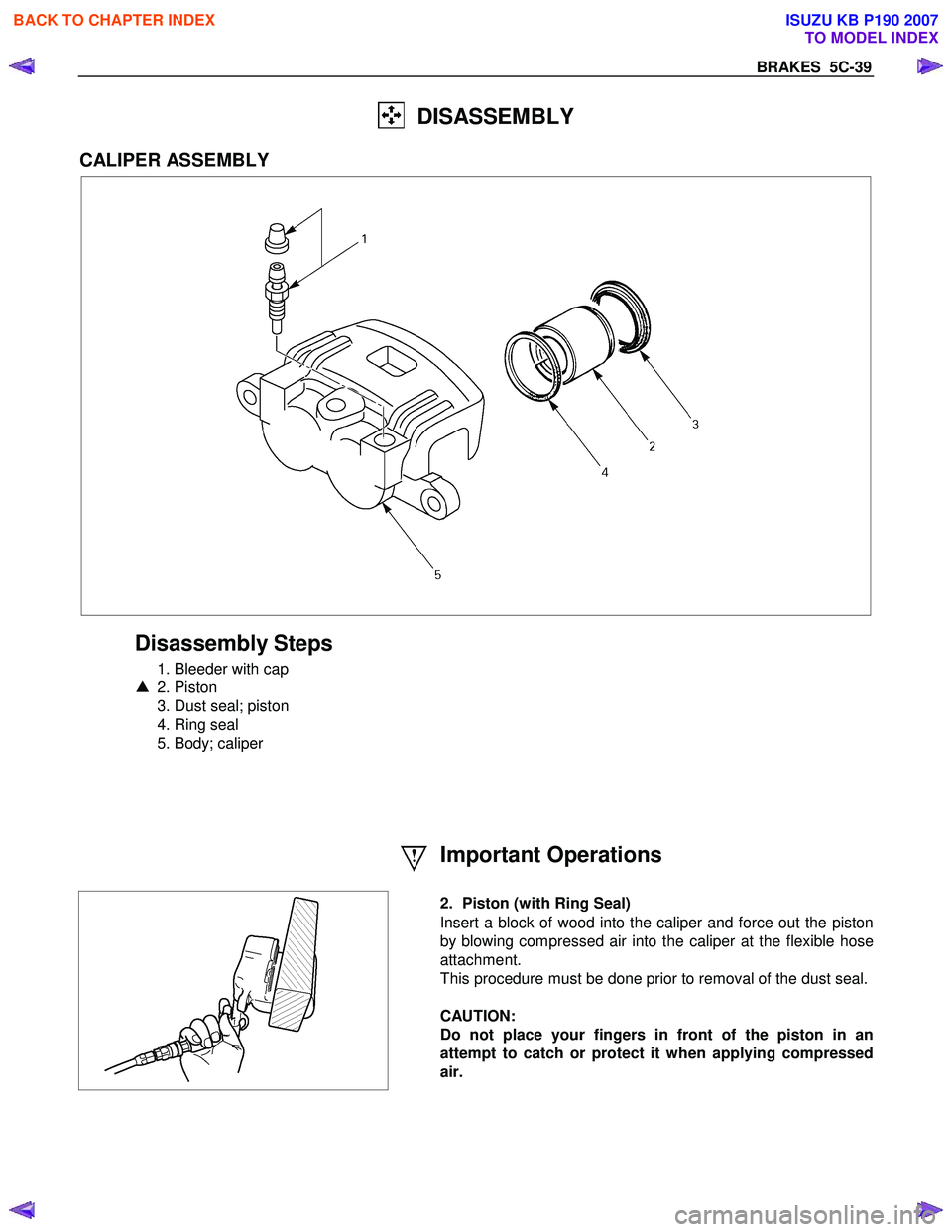
CALIPER ASSEMBLY
Disassembly Steps
1. Bleeder with cap
▲ 2. Piston
3. Dust seal; piston
4. Ring seal
5. Body; caliper
Important Operations
2. Piston (with Ring Seal)
Insert a block of wood into the caliper and force out the piston
by blowing compressed air into the caliper at the flexible hose
attachment.
This procedure must be done prior to removal of the dust seal.
CAUTION:
Do not place your fingers in front of the piston in an
attempt to catch or protect it when applying compressed
air.
BACK TO CHAPTER INDEX
TO MODEL INDEX
ISUZU KB P190 2007
Page 739 of 6020
5C-40 BRAKES
INSPECTION AND REPAIR
Make necessary correction or parts replacement if wear damage or any other abnormal conditions are found
through inspection.
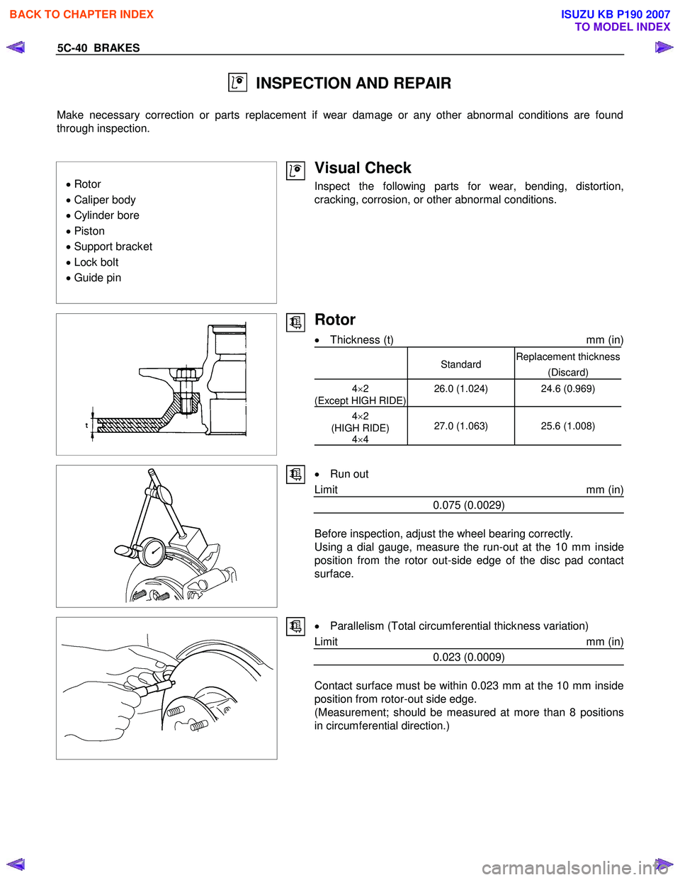
• Rotor
• Caliper body
• Cylinder bore
• Piston
• Support bracket
• Lock bolt
• Guide pin
Visual Check
Inspect the following parts for wear, bending, distortion,
cracking, corrosion, or other abnormal conditions.
Rotor
• Thickness (t) mm (in)
StandardReplacement thickness
(Discard)
4×2
(Except HIGH RIDE) 26.0 (1.024)
24.6 (0.969)
4×2
(HIGH RIDE) 4×4 27.0 (1.063) 25.6 (1.008)
•
Run out
Limit mm (in)
0.075 (0.0029)
Before inspection, adjust the wheel bearing correctly.
Using a dial gauge, measure the run-out at the 10 mm inside
position from the rotor out-side edge of the disc pad contact
surface.
•
Parallelism (Total circumferential thickness variation)
Limit mm (in)
0.023 (0.0009)
Contact surface must be within 0.023 mm at the 10 mm inside
position from rotor-out side edge.
(Measurement; should be measured at more than 8 positions
in circumferential direction.)
BACK TO CHAPTER INDEX
TO MODEL INDEX
ISUZU KB P190 2007
Page 740 of 6020
BRAKES 5C-41
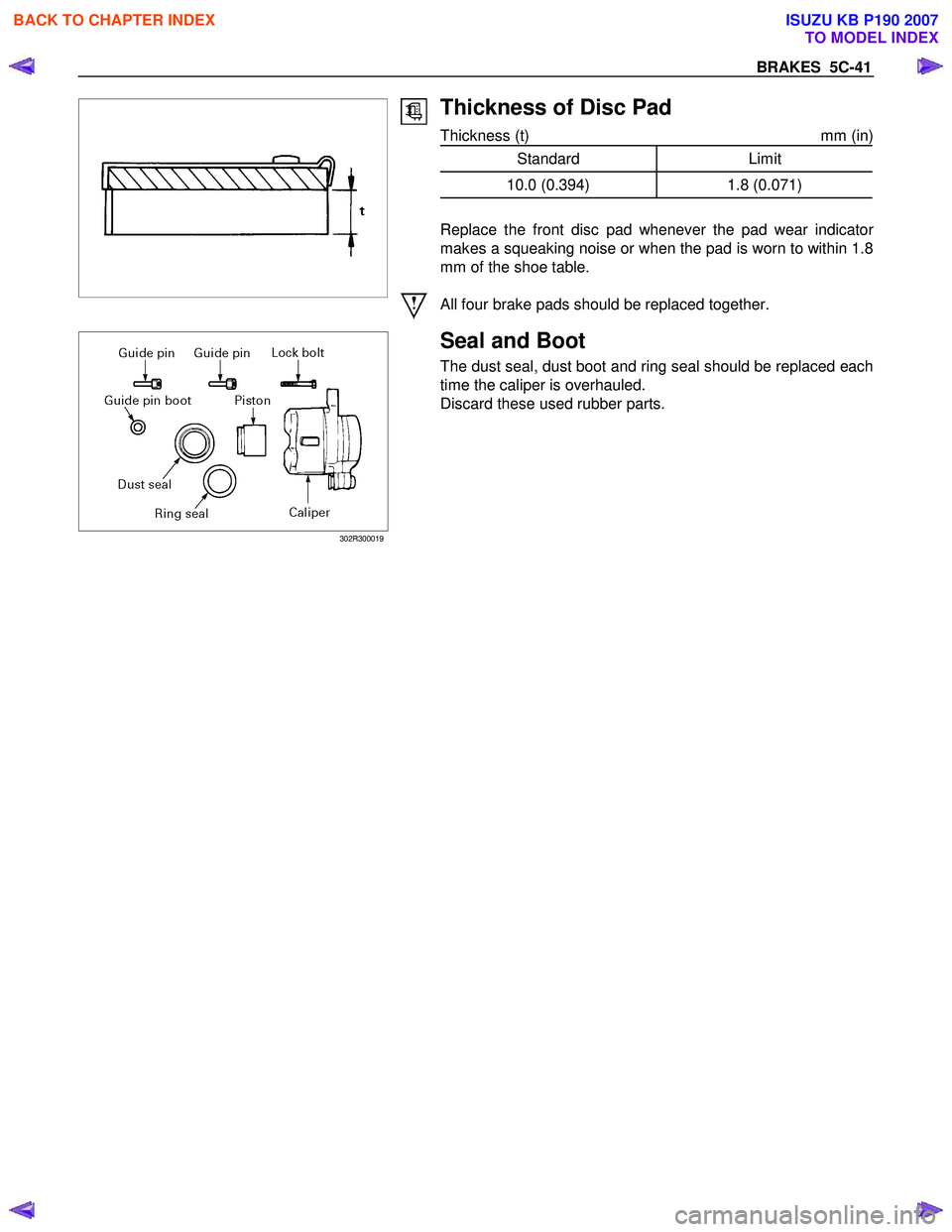
Thickness of Disc Pad
Thickness (t) mm (in)
Standard Limit
10.0 (0.394) 1.8 (0.071)
Replace the front disc pad whenever the pad wear indicato
r
makes a squeaking noise or when the pad is worn to within 1.8
mm of the shoe table.
All four brake pads should be replaced together.
302R300019
Seal and Boot
The dust seal, dust boot and ring seal should be replaced each
time the caliper is overhauled.
Discard these used rubber parts.
BACK TO CHAPTER INDEX
TO MODEL INDEX
ISUZU KB P190 2007