MAZDA PROTEGE 1992 Workshop Manual
Manufacturer: MAZDA, Model Year: 1992, Model line: PROTEGE, Model: MAZDA PROTEGE 1992Pages: 1164, PDF Size: 81.9 MB
Page 791 of 1164

OUTSIDE MIRROR S
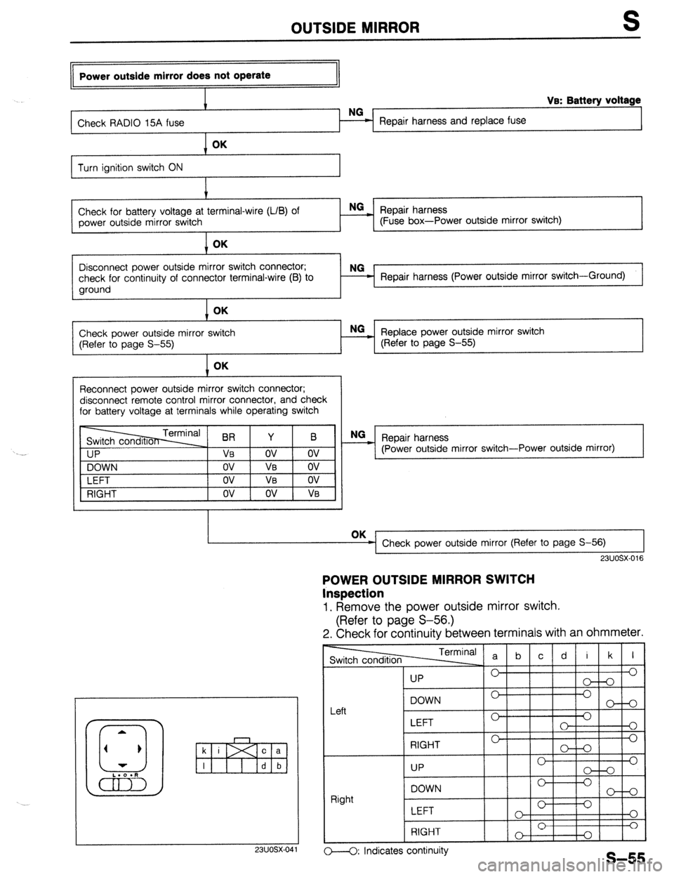
Power outside mirror does not operate
I
I VB: Battery voltage
Check RADIO 15A fuse Repair harness and replace fuse OK
Turn ignition switch ON
I.’
Check for battery voltage at terminal-wire (LIB) of NG
_ Repair harness
power outside mirror switch (Fuse box-Power outside mirror switch) OK
1
I
Disconnect power outside mirror switch connector;
check for continuity of connector terminal-wire (B) to
ground Repair harness (Power outside mirror switch-Ground)
Check power outside mirror switch
(Refer to page S-55) OK
- Replace power outside mirror switch NO
(Refer to page S-55)
Reconnect power outside mirror switch connector;
disconnect remote control mirror connector, and check
for battery voltage at terminals while operating switch
I IP
NG
_ Repair harness
(Power outside mirror switch-Power outside mirror)
VI
DOWN
LEFT
RIGHT OK
Check power outside mirror (Refer to page S-56) I I
23UOSX-016
POWER OUTSIDE MIRROR SWITCH
Inspection
1. Remove the power outside mirror switch.
(Refer to page S-56.)
2. Check for continuity between terminals with an ohmmeter.
23UOSX-04
TermIn:
-1
I I
UP 0’
LEFT 0
0
o---O: Indicates continuity
Page 792 of 1164

OUTSIDE MIRROR
c a
23UOSX.042
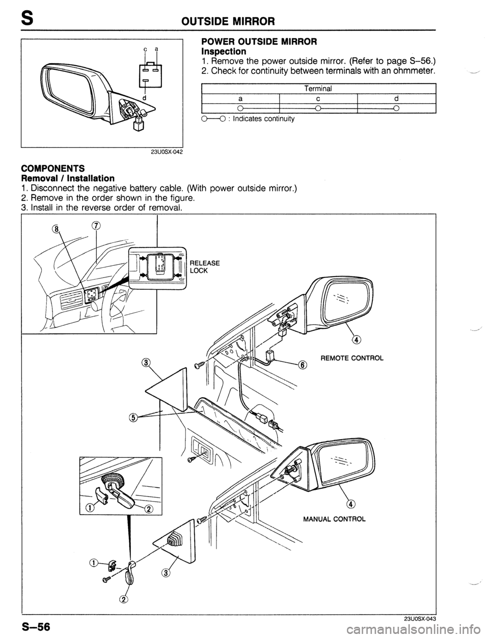
POWER OUTSIDE MIRROR
Inspection
1. Remove the power outside mirror. (Refer to page S-56.)
2. Check for continuity between terminals with an ohmmeter.
I
Terminal I
t
a C d
0 I
A I
0
o--O : indicates continuity
COMPONENTS
Removal / Installation
1. Disconnect the negative battery cable. (With power outside mirror.)
2. Remove in the order shown in the figure.
3. Install in the reverse order of removal.
MANUAL CONTROL
S-56
Page 793 of 1164

OUTSIDE MIRROR S
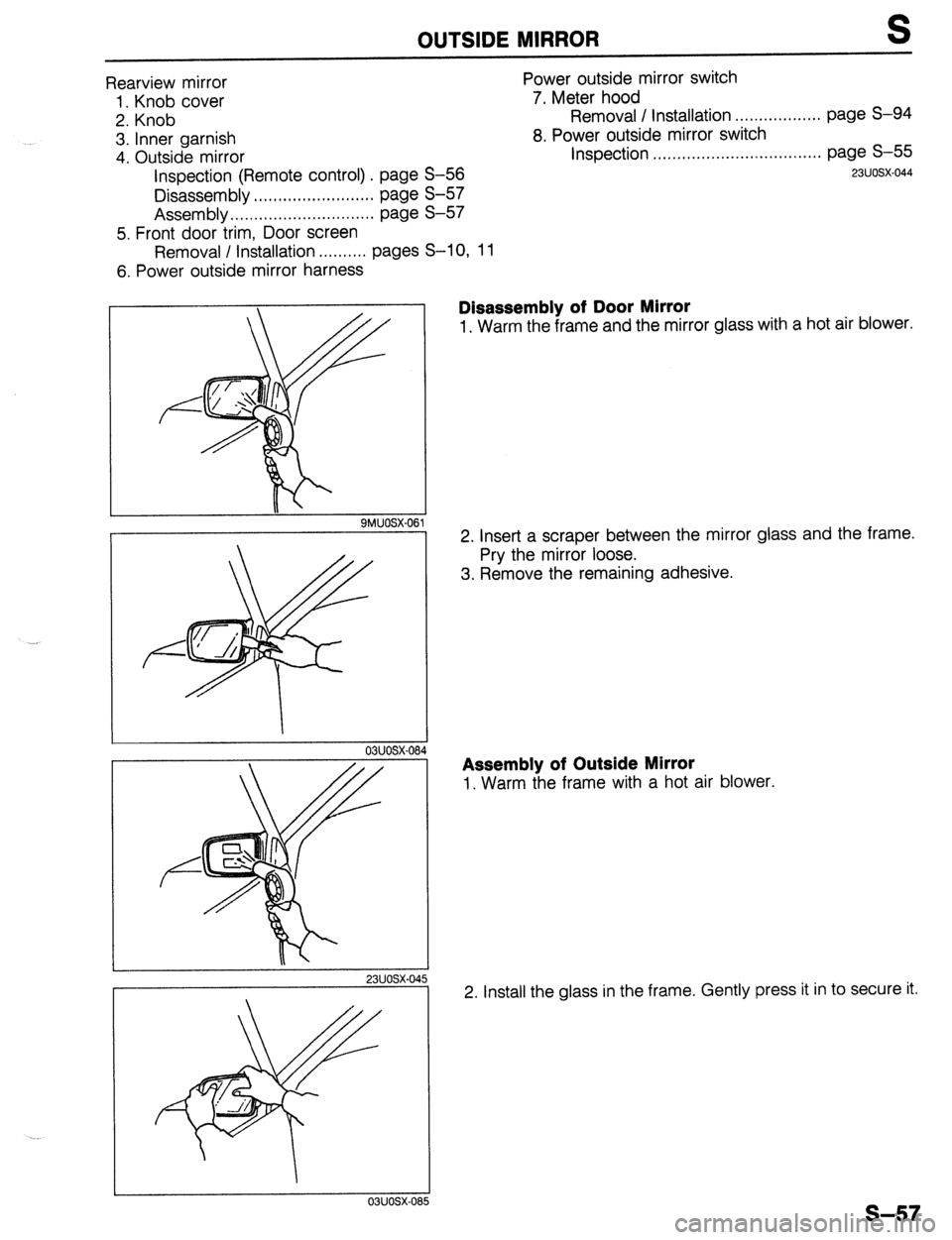
Rearview mirror
1. Knob cover
2. Knob
3. Inner garnish
4. Outside mirror
Inspection (Remote control) . page S-56
Disassembly . . .., ,.,...... ,., ,. . . . . . . page S-57
Assembly.. . . . . . . . . . . . . . . . . . . . . . . . . . . . . page S-57
5. Front door trim, Door screen Power outside mirror switch
7. Meter hood
Removal / installation . . . . . . . . . . . . . . . . . . page S-94
8. Power outside mirror switch
Inspection .,,....,..,...,..........., . . . . . . . . page S-55
23UOSX-044
Removal / Installation . . . . . . . . . . pages S-l 0, 11
6. Power outside mirror harness
. .
23UOSX-04
Disassembly of Door Mirror
1. Warm the frame and the mirror glass with a hot air blower.
2. Insert a scraper between the mirror glass and the frame.
Pry the mirror loose.
3. Remove the remaining adhesive.
Assembly of Outside Mirror
1. Warm the frame with a hot air blower.
2. Install the glass in the frame. Gently press it in to secure it.
s-57
Page 794 of 1164

S WINDSHIELD
WINDSHIELD
PREPARATION
SST
49 0305 870A I 1 For
Tool set, window removal and
installation of
windshield
COMPONENTS
Removal / Installation
1. Disconnect the negative battery cable.
2. Remove in the order shown in the figure, referring to
Removal Note.
3. Install in the reverse order of removal, referring to Installation Note.
PROTEGC
Page 795 of 1164

WINDSHIELD S
1. Sun visor and adaptor 7. Glass stopper
2. Inside rearview mirror, overhead console 8. A-pillar garnish (Hatchback)
(With sliding sunroof) Removal / Installation . . . . . . . . . . . . . . . . . . page S-42
3. A-pillar trim 9. Upper windshield molding
Removal / Installation ..,.,..... pages S-97, 98 Removal / Installation . . . . . . . . . . . . . . . . . . page S-42
4. Upper garnish 10. Windshield
5. Wiper arm and blade Removal Note .,.....*.........*........... page S-59
Removal / Installation . . . . . . . . . . . . page S-72 Installation Note ..,......*................ page S-60
6. Cowl arille 11. Spacer
Removal I Installation . . . . . . . . . . . . page S-53 12. Protector
1 HEADLINER
Gsi?i==
SiX.A-A
03uosx-08
PROTECTIVE TAPE -I
9 03UOSX-088
Removal Note
Windshield
1, Use protective tape or cloth along the front edge of the head-
liner to protect it from damage.
2. Apply protective tape along the edge of the body.
3. Using an awl, make a hole through the sealant from the in-
side of the vehicle.
4. Pass piano wire through the hole.
5. Wind each end of the wire around a bar.
6. Working with another person, saw through the sealant
around the edge of the glass. Then remove the glass.
Caution
l Use a long sawing action to spread the work over
the whole length of wire to prevent if from breaking.
l Be careful that the wire does not rub on the body
or dash panel.
Note
l If the glass is not to be reused, a tool like that shown
in the figure may be used.
Insert the blade in the sealant, and pull on the bars.
s-59
Page 796 of 1164

WINDSHIELD
mm (in)
03uosx-09
________
03uosx 09
(PROTEGt) 4
(HATCHBACK) ;
F I
I
B
Installation Note
Windshield
1. Cut away the old sealant with a razor knife so that 1 to 2mm
(0.04 to 0.08 in) of sealant remains around the circumfer-
ence of the frame. If all the sealant has come off in any one
place, apply primer after degreasing, and allow it approx.
30 minutes to dry. Then put on new sealant to create a
2mm (0.08 in) layer. _,
2. Carefully clean an area 5 cm (1.97 in) wide around the cir-
cumference of the glass and the bond on the body.
3. Bond a new dam along the circumference of the glass 7mm
(0.28 in) from the edge.
Caution
l Bond the dam securely and allow it to dry.
4. Apply primer with a brush to the bonding area of the glass
and the body, and allow it to dry for approx. 30 minutes.
Caution
l Keep the area free of dirt and grease. Do not touch
the surface. If primer gets on the hands, remove it
immediately.
5. Apply primer to the upper windshield molding as shown.
Caution
l Keep the area free of dirt and grease. Do not touch
the surface.
0:1IJosx 096
6. Install the spacers onto the body as shown
Caution
. Damaged spacers must be replaced.
o3uosx~o97
S-60
Page 797 of 1164

WINDSHIELD S
PROTECTOR
I SEALANT
mm (in)
.
03uosx-09
GLASS /
SPACER
mm (in
03uosx-1c
PROTEG6
MOLDING MOLDING
SEALANT SEALANT
CROSS-SECTION
mm (in)
03uosx-1c
7. Align the protector on the body, and attach it securely as
shown.
8. Prepare the nozzle of the sealant gun so that it has a flange
that can run along the edge of the glass and a V from which
the sealant can flow. Once the primer is dry, apply the seal-
ant around the entire circumference of the glass to fill the
gap between the dam and the edge of the glass with a ridge
of sealant
12mm (0.47 in) high.
Keep the bead of sealant smooth and even, reshaping it
where necessary with a spatula.
9. Lift the glass into place. Push it in lightly toward the vehicle
to compress the sealant.
Caution
l Open the windows to prevent the glass from being
pushed out by air pressure if a door is closed.
Hardening time of repair seal
I Temperature Surface hardening Time required until car
time can be put into service
I
5% (41 OF) Approx. 1.5 hrs 12 hrs
2ooc (68OF) Approx. 1 hr
4 hrs
35OC (95OF)
Approx. 10 min 2 hrs
10. Align the upper windshield molding on the body as shown,
and push the molding into place along the top.
Note
l Install the molding before the sealant has hardened.
11. Check for water leaks. If a leak is found, wipe the water off
well and add
sealant (BOO1 77 739) where needed.
S-61
Page 798 of 1164

QUARTER WINDOW GLASS
QUARTER WINDOW GLASS
COMPONENTS
Removal / Installation
1, Remove in the order shown in the figure.
2. Install in the reverse order of removal.
Note
l Remove overlapping portion of the quarter trim for removal of the A-pillar trim (U.S.) or B-
pillar upper trim (Canada).
7.8-l 1 N.m (80-I 10 cm-kg, 69-95 in-lb)
9
1. Seat belt upper anchor (Canada) 3. Quarter window lock
Removal / Installation . . . . . . . . . . . . . . . . page S-100 4. Quarter window glass
2. A-pillar trim (U.S.)/B-pillar upper trim (Canada) 5. Quarter window hinge
Removal I Installation . . . . . . . . . . . . . . . . page S- 98 6. Pillar molding
S-62
Page 799 of 1164

REAR WINDOW GLASS S
REAR WINDOW GLASS
PREPARATION
SST
49 0305 870A
1 For
Tool set, window removal and
installation of rear
window glass
COMPONENTS
Removal / Installation
1. Disconnect the negative battery cable.
2. Remove in the order shown in the figure, referring to
Removal Note.
3. install in the reverse order of removal, referring to Installation Note.
r
I’
PROTEGi:
1. Rear seat cushion
6. Rear header trim
5
Removal I Installation . . . . . . . . . . . . . . . . page S-l 11
Removal / Installation . . . . . . . . . . . . . . . . page S-
97
2. Rear seat back/side
7. C-pillar trim
Removal I Installation . . . . . . . . . . . . . . . . page S-l 11
3. High-mount stoplight (interior mounted)
Removal / Installation . . . . . . . . . . . . . . . . . . . . . Section
T
4. Rear package trim
Removal I Installation . . . . . . . . . . . . . . . . page S-
97
5. Rear seat belt upper anchor
Removal / Installation ..,............. page
S-101
Removal / Installation . . . . . . . . . . . . . . . . page S-
97
8. Rear window molding
Removal I Installation . . . . . . . . . . . . . . . . page S-
43
9. Rear window glass
Removal Note . . . . . . . . . . . . . . . . . . . . . . . . . . .
page S- 64
Installation Note . . . . . . . . . . . . . . . . . . . . . . . . page S-
65
10. Spacer
S-63
Page 800 of 1164

S REAR WINDOW GLASS
HATCHBACK
1
J
03UOSX-106
1. Rear wiper arm and blade
Removal / Installation . . . . . . . . . . . . . . . . . . page S-78
2. Rear window molding
Removal. . . . . . . . . . . . . . . . . . . . . . . . . . . . . . . page S-44
Installation . . . . .,...,........................ page S-45
3. Rear hatch lower trim 4. Seaming welt
5. Rear window glass
Removal Note ..,.,,,.......,.............. page S-64
Installation Note . . . . . . . . . . . . . . . . . . . . . . . . . . page S-65
6. Spacer ‘.-
Removal / Installation . . . . . . . . . . . . . . . . page S-98
Removal Note
PROTECTIVE TAPE Rear window glass
1. Apply protective tape along the edge of the body to pro-
tect it from damage.
2. Using an awl, make a hole through the sealant from the in-
side of the vehicle.
3. Pass piano wire through the hole.
4. Wind each end of the wire around a bar.
5. Working with another person, saw through the sealant
around the edge of the glass. Then remove the glass.
Caution
l Use a long sawing action to spread the work over
the whole length of wire to prevent it from breaking.
l Be careful that the wire does not rub on the body.
I SMUOSX-139