JAGUAR X308 1998 2.G Workshop Manual
X308 1998 2.G
JAGUAR
JAGUAR
https://www.carmanualsonline.info/img/21/7640/w960_7640-0.png
JAGUAR X308 1998 2.G Workshop Manual
Trending: wheel torque, 303-14, oil, Cooling, body mounting, recommended oil, charger
Page 201 of 2490
I
nstallation
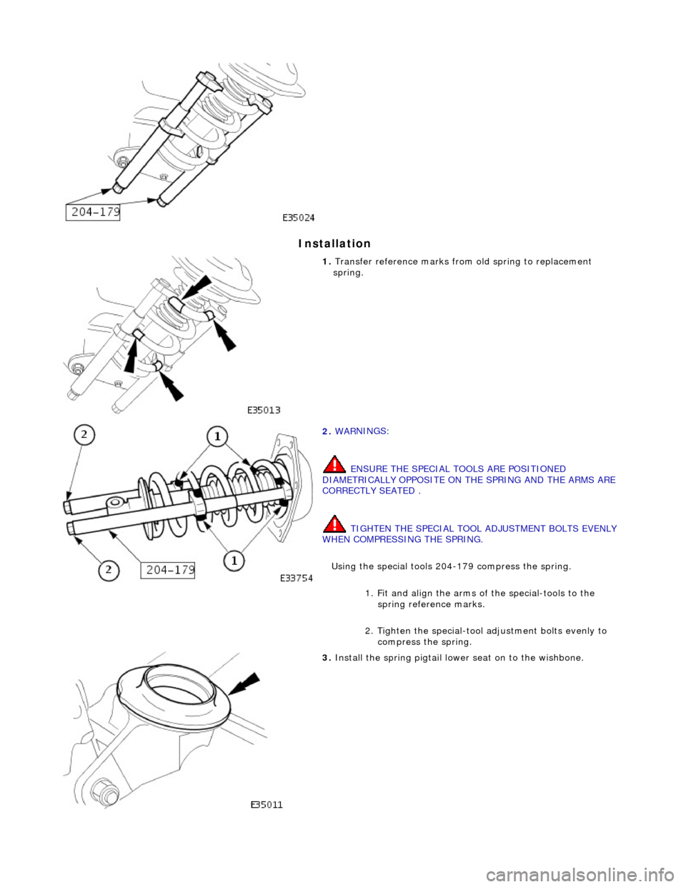
1.
Transfer r
eference marks from
old spring to replacement
spring.
2. WAR
NINGS:
ENSURE THE SPECIAL TOOLS ARE POSITIONED
DIAMETRICALLY OPPOSITE ON THE SPRING AND THE ARMS ARE
CORRECTLY SEATED .
TIGHTEN THE SPECIAL TOOL ADJUSTMENT BOLTS EVENLY
WHEN COMPRESSING THE SPRING.
Using the special tools 204-179 compress the spring.
1. Fit and align the arms of the special-tools to the spring reference marks.
2. Tighten the special-tool adjustment bolts evenly to compress the spring.
3. Install th
e spring pigtail lower seat on to the wishbone.
Page 202 of 2490
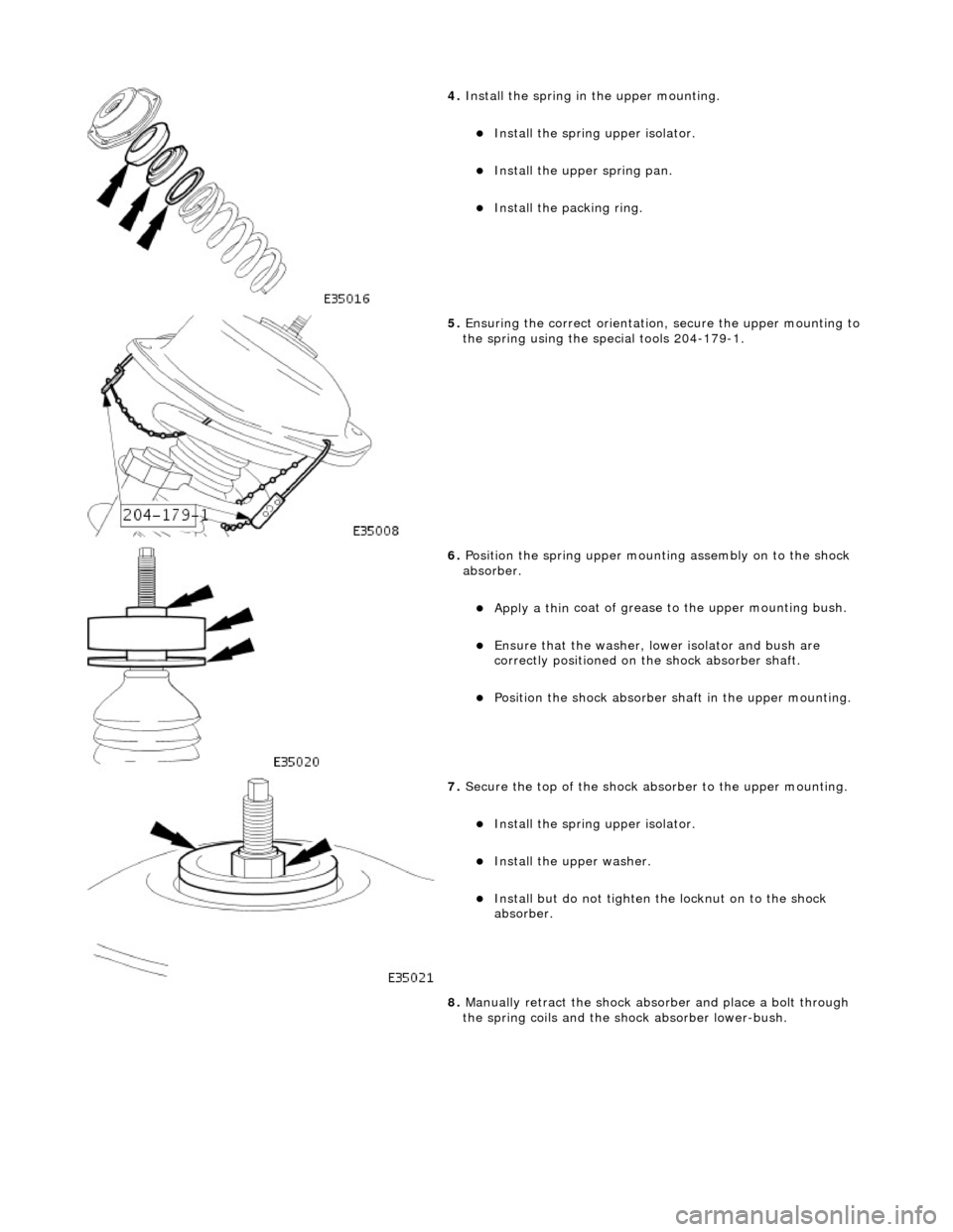
4. Install the spri
ng in
the upper mounting.
Install the spri
ng upper isolator.
Install
the up
per spring pan.
Inst
al
l the packing ring.
5. Ensuri ng the correct orientati
on,
secure the upper mounting to
the spring using the special tools 204-179-1.
6. Position the spri ng
upper mounting assembly on to the shock
absorber.
Apply a th in
coat of grease to the upper mounting bush.
E
n
sure that the washer, lo
wer isolator and bush are
correctly positioned on the shock absorber shaft.
Po si
tion the shock absorber shaft in the upper mounting.
7. Sec
ure the top of the shock ab
sorber to the upper mounting.
Install the spri
ng upper isolator.
Inst
al
l the upper washer.
In
s
tall but do not tighten the locknut on to the shock
absorber.
8. Manually retract the shock abso rber and place a bolt through
the spring coils and the sh ock absorber lower-bush.
Page 203 of 2490
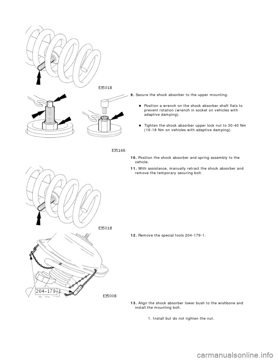
9. Se
cure the shock absorber
to the upper mounting.
Posi
tion a wrench on the shock absorber shaft flats to
prevent rotation (wrench in socket on vehicles with
adaptive damping).
Tigh
ten the shock absorber upper lock nut to 30-40 Nm
(16-18 Nm on vehicles with adaptive damping).
10. Position the shock absorber and spring assembly to the
vehicle.
11
.
With assistance, manually re tract the shock absorber and
remove the temporary securing bolt.
12
.
Remove the special tools 204-179-1.
13. Align the shock absorber lower bush to the wishbone and
install the mounting bolt.
1. Install but do not tighten the nut.
Page 204 of 2490
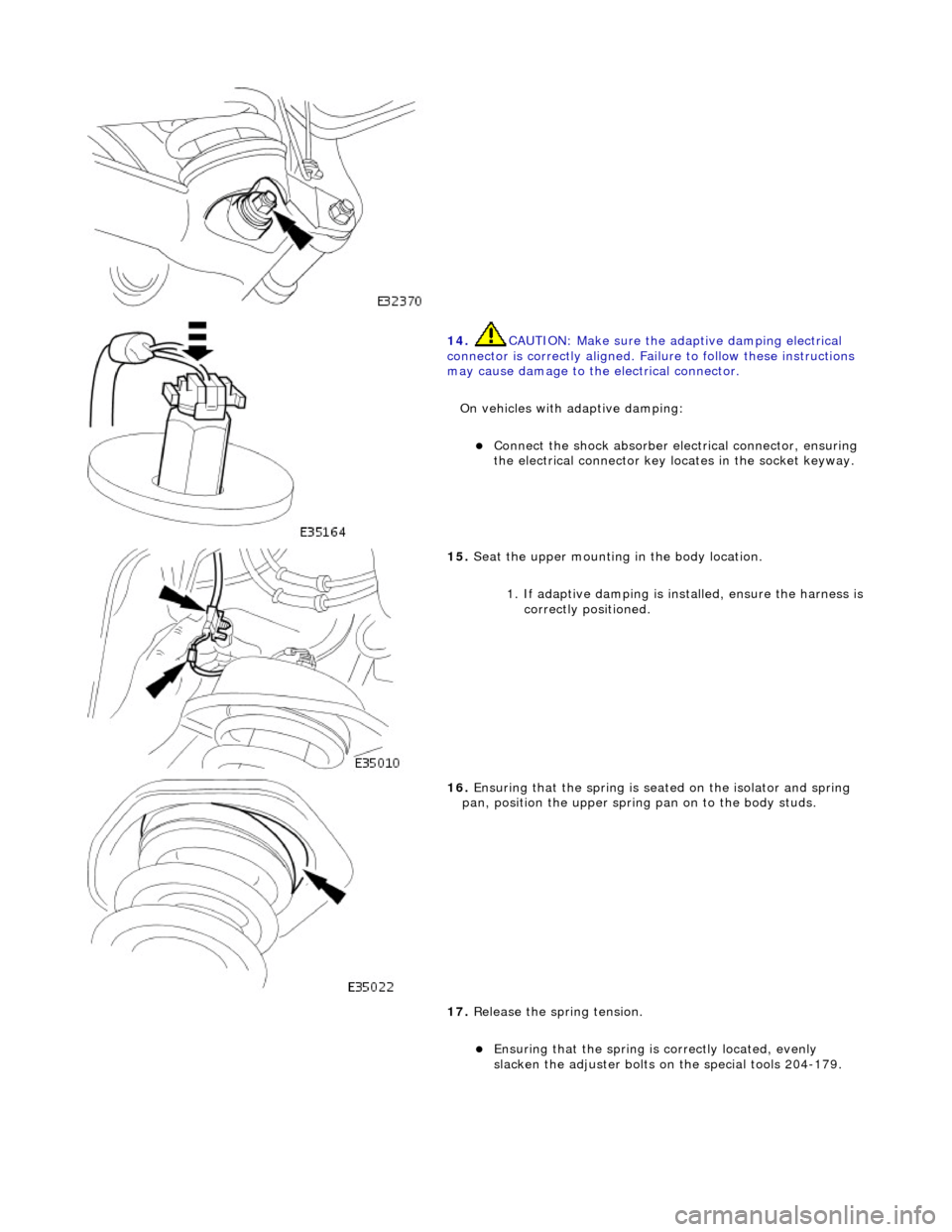
14. CAUTI
ON: Make sure the adaptive damping electrical
connector is correctly aligned. Failu re to follow these instructions
may cause damage to the electrical connector.
On vehicles with adaptive damping:
Conne ct
the shock absorber elec
trical connector, ensuring
the electrical connector key locates in the socket keyway.
15 . Seat
the upper mounting in the body location.
1. If adaptive damping is installed, ensure the harness is
correctly positioned.
16 . Ensuri
ng that the spri
ng is seated on the isolator and spring
pan, position the u pper spring pan on to the body studs.
17. Release the spring tension.
Ensuring that the spri
ng is
correctly located, evenly
slacken the adjuster bolts on the special tools 204-179.
Page 205 of 2490
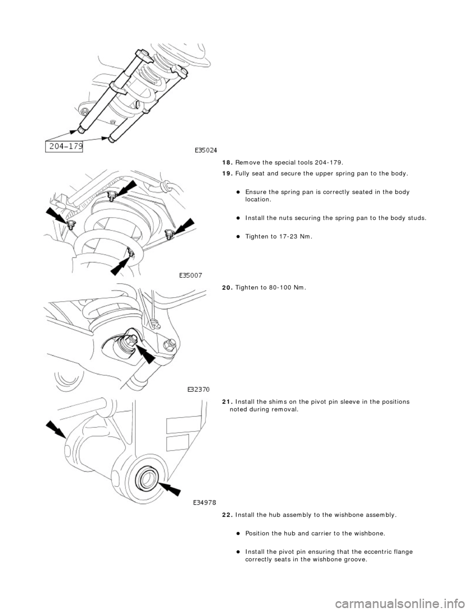
18
.
Remove the special tools 204-179.
19
.
Fully seat and secure the u pper spring pan to the body.
Ensure the spri
ng pan is correctly seated in the body
location.
Inst
all the nuts securing the sp
ring pan to the body studs.
Tigh
ten to 17-23 Nm.
20
.
Tighten to 80-100 Nm.
21
.
Install the shims on the pivot pin sleeve in the positions
noted during removal.
22. Install the hub assembly to the wishbone assembly.
Position the hub and carri
er to the wishbone.
Inst
all the pivot pin ensuring that the ecce
ntric flange
correctly seats in the wishbone groove.
Page 206 of 2490
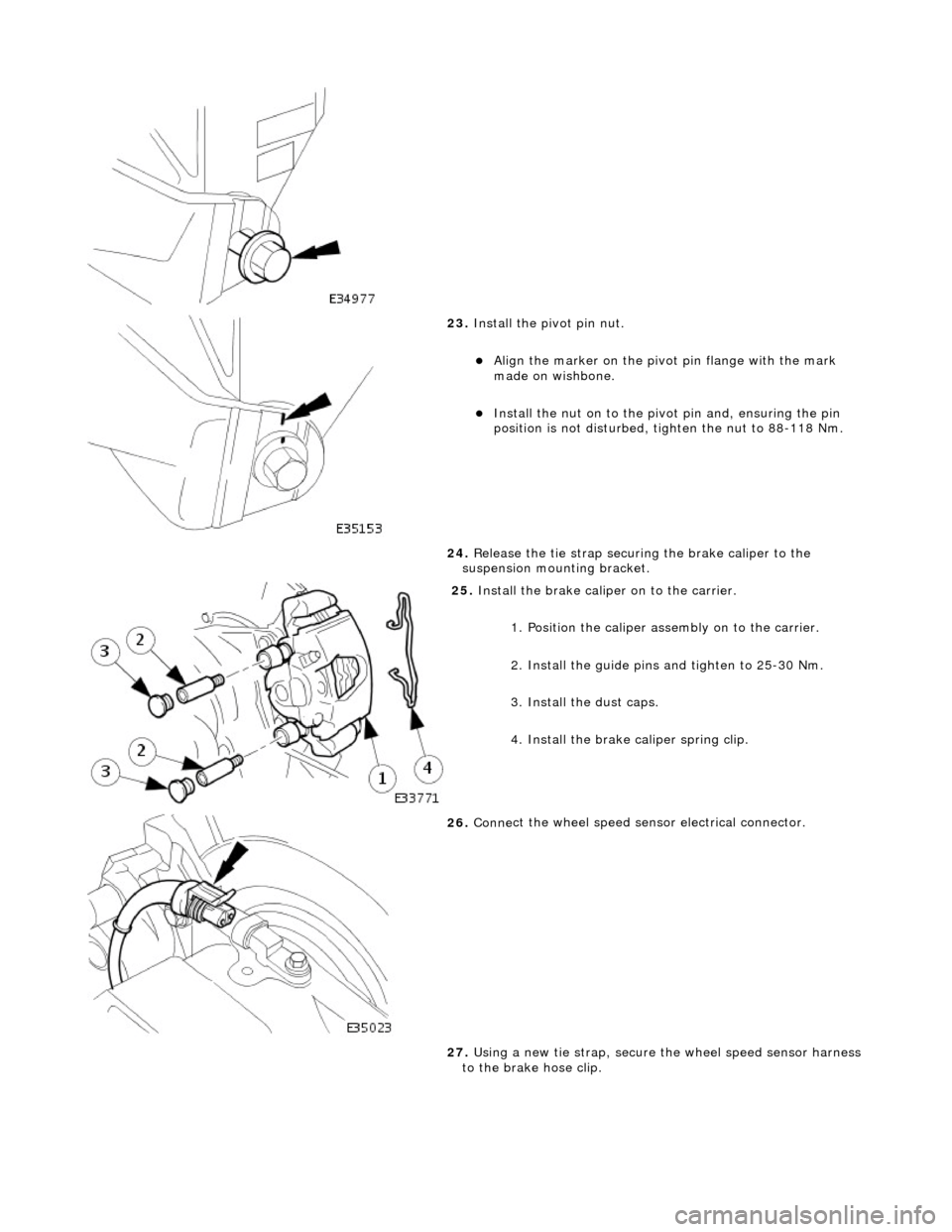
23. Inst
all the pivot pin nut.
Ali
g
n the marker on the pivo
t pin flange with the mark
made on wishbone.
Inst al
l the nut on to the pivot pin and, ensuring the pin
position is not dist urbed, tighten the nut to 88-118 Nm.
24. Release the tie strap securing the brake caliper to the
suspension mounting bracket.
25 . Install
the brake caliper on to the carrier.
1. Position the caliper asse mbly on to the carrier.
2. Install the guide pins and tighten to 25-30 Nm.
3. Install the dust caps.
4. Install the brake caliper spring clip.
26 . Conne
ct the wheel speed sensor electrical connector.
27. Using a new tie strap, secure the wheel speed sensor harness
to the brake hose clip.
Page 207 of 2490
28
.
Install the rear wheel.
For additional informat ion, refer to Section 204
-04
Wheels and
Tire
s
.
29
.
Remove the axle stands and lower the vehicle.
For additional informat ion, refer to Section 100
-0
2 Jacking and
Liftin
g
.
30
.
Check and adjust the rear whee l alignment as necessary.
For additional informat ion, refer to Section 204
-00
Suspension
Sy
stem
- General
Information
.
Page 208 of 2490
St
abilizer Bar Vehicles With: Supercharger
64.35.08
Rubber Suspension Insulator Lube
Castrol NTR
Removal
1.
CA
UTION:
Replacement of nuts and bolts: Various thread-locking devices are used on nuts and bolts
throughout the vehicle. These devices restrict the number of times a nut or bolt can be used. See
section <<100-00>>
for information.
Raise vehicle on a four-post lift. Refer to section <<100-02>>.
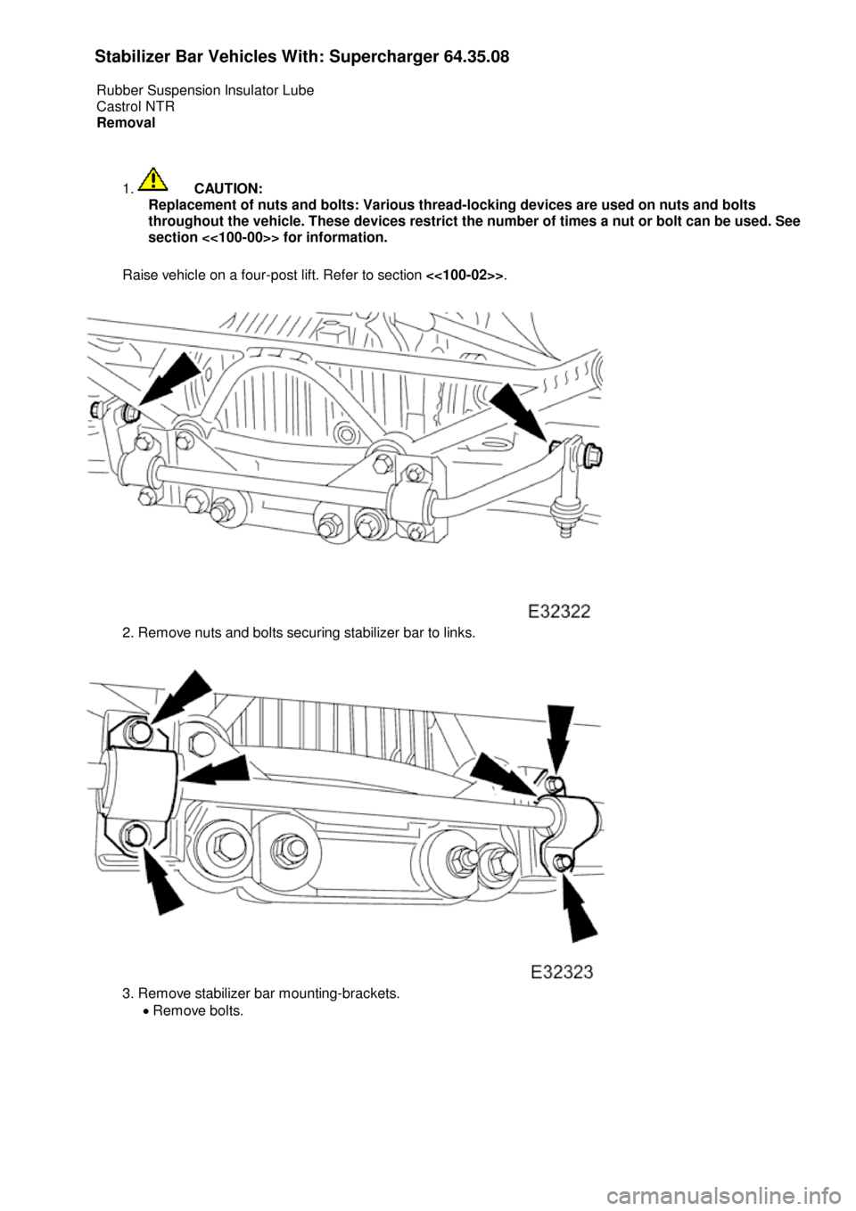
2.
Remove nuts and bolts securing stabilizer bar to links.
3.
Remove stabilizer bar mounting-brackets.
Remove bolts.
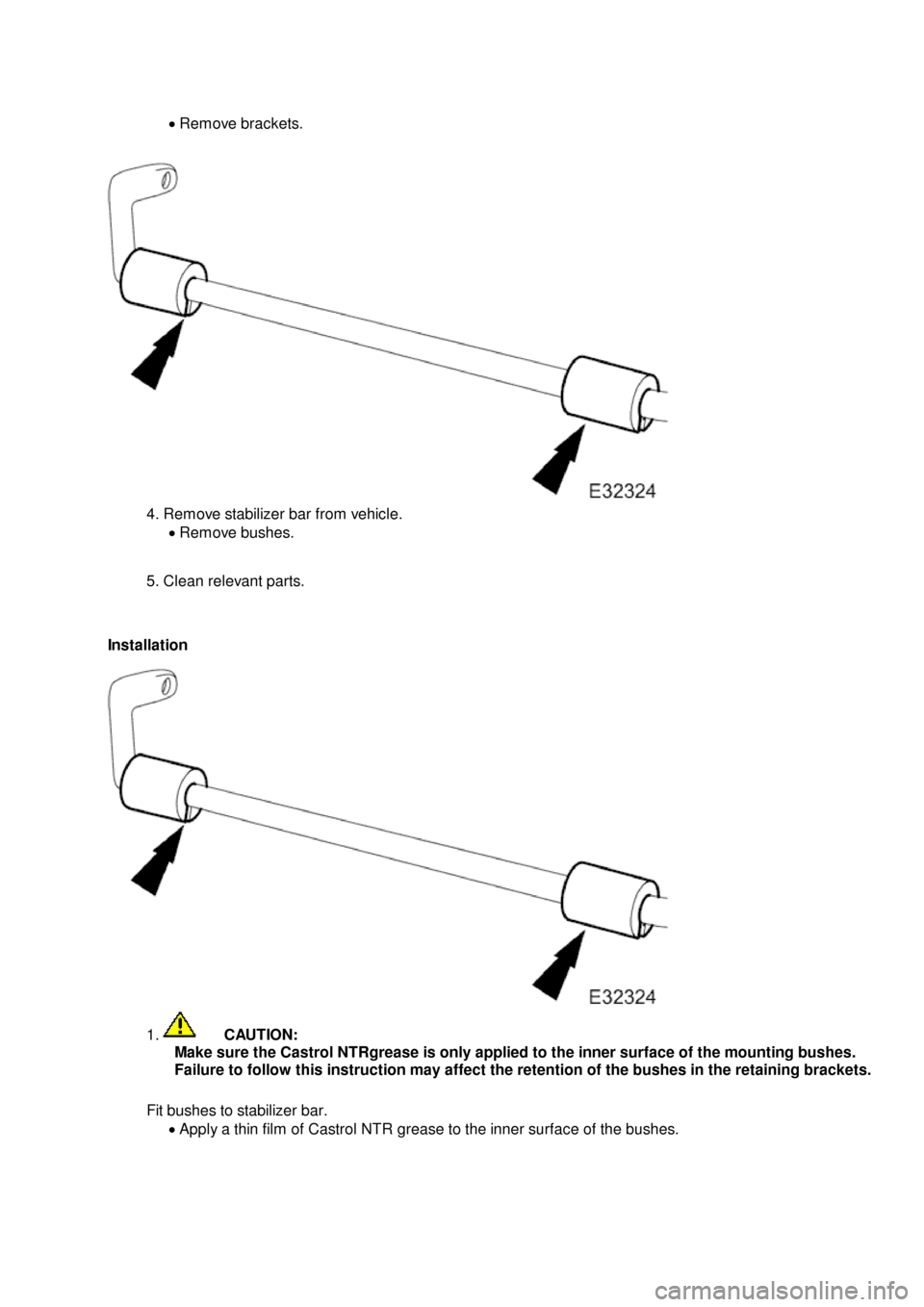
Page 209 of 2490
Remove brackets.
4
. Remove stabilizer bar from vehicle.
Remove bushes.
5. Clean relevant parts.
Installation
1
.
C
AUTION:
Make sure the Castrol NTRgrease is only applied to the inner surface of the mounting bushes.
Failure to follow this instruction may affect the retention of the bushes in the retaining brackets.
Fit bushes to stabilizer bar. Apply a thin film of Castrol NTR grease to the inner surface of the bushes.
Page 210 of 2490
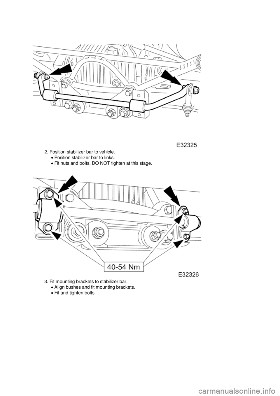
2.
Position stabilizer bar to vehicle.
Position stabilizer bar to links.
Fit nuts and bolts, DO NOT tighten at this stage.
3.
Fit mounting brackets to stabilizer bar.
Align bushes and fit mounting brackets.
Fit and tighten bolts.
Trending: fuel injection, air filter, window, lights, headlamps, tow bar, jacking points
